Modbus FAQ
General
1. What is MODBUS?
MODBUS is a commonly used industrial communications protocol. It allows the exchange of data between PLCs and computers. It was originally designed for Modicon (Schneider Electric) PLCs but has become widely used by many PLC manufacturers and industrial networks.
2. Why would I use MODBUS?
MODBUS is a common means of gathering data from many different sources for viewing operations, archiving and troubleshooting from a central remote location. It is widely used and a fairly simple protocol. Depending on the application a newer protocol may have more advantage.
Typically a PC is set up running such programs as Wonderware, Intellution or LabVIEW in one location to gather data from various processes around the factory. Another application is for setting up remote factory process controllers (such as other PLCs like Allen-Bradley, Siemens, PLCDirect, etc.) to respond to different levels or modes that are being transmitted from the device.
3. How does it work?
Devices using MODBUS communicate using a master-slave technique, in which only one device (the master) can initiate transactions (queries). The other devices (the slaves) respond by supplying the requested data to the master, or by taking the action requested in the query. The master can address individual slaves, or can initiate a broadcast message to all slaves. Slaves return a message (response) to queries that are addressed to them individually.
The History | Specifications | Modbus Organization">Modbus protocol establishes the format for the master's query by placing into it the device (or broadcast) address, a function code defining the requested action, any data to be sent, and an error-checking field. The slave's response message is also constructed using Modbus protocol. It contains fields confirming the action taken, any data to be returned, and an error-checking field. If an error occurred in receipt of the message, or if the slave is unable to perform the requested action, the slave will construct an error message and send it as its response.
4. Is MODBUS Plus the same as MODBUS?
No, they are different protocols and not compatible. To link the two protocols a converter like Panel-Tec’s MD3000 is needed. This FAQ only applies to Modbus serial communications.
5. Is MODBUS TCP/IP the same as MODBUS?
No, they are different protocols and not compatible. A converter from MODBUS serial to MODBUS TCP/IP Ethernet is needed (for instance the EIS-2B Series Industrial MicroServers from Omega Engineering). This FAQ only applies to Modbus serial communications.
6. Where can I find out more about MODBUS?
- Modicon’s MODBUS Protocol Guide: http://www.modicon.com/techpubs/toc7.html
- The MODBUS Users Web Site: http://www.modbus.org/
Networking
7. What is a master-slave network?
A master-slave technique is one in which only one device (the master) can initiate transactions (queries). The other devices (the slaves) respond by supplying the requested data to the master, or by taking the action requested in the query. Typical master devices include touch screens or PCs running Wonderware, Intellution or LabVIEW while slaves include PLCs and smart devices such as PID controllers or meters.
8. How can I connect MODBUS devices together in a network?
RS-232 outputs cannot be connected together. To create a network the devices must use a RS-485 network and have a unique slave address.
References:
- AutomationDirect FA-ISOCON manual: http://www.facts-eng.com/manuals/faisoconm.pdf
- Dataforth DCP485 manual: http://www.dataforth.com/catalog/pdf/DCP485.pdf
9. What are RS-232, RS-422 and RS-485 and how are they different?
These are standards for serial communications that define the pin outs, cabling, signal levels, transmission baud rates and parity checking.
- RS-232 only allows for one master and one slave and is limited to distances of up to 15 meters.
- RS-422 can address up to 10 slaves using four wires (full duplex) and has a distance capacity of 4000 meters.
- RS-485 can address up to 32 slaves using either a two wire (half duplex) or four wire system (full duplex) and has a distance capacity of 4000 meters.
A common mistake is to confuse the electrical standard with the protocol. Protocols define how the data is structured while the electrical standards determine how the data is physically transmitted. There are many different protocols (i.e. Modbus, DF1, AS511) that can be used on RS-232, RS-422 or RS-485 wired systems.
References:
- The RS232 Standard: http://www.camiresearch.com/Data_Com_Basics/RS232_standard.html
- Basics of the RS485 Standard: http://www.bb-elec.com/tech_articles/rs485_basics.asp
10. How many slaves can there be?
- RS-232 only allows for one slave.
- RS-422 can address up to 10 slaves.
- RS-485 can address up to 32 slaves.
The address can be a unique number between 1 and 247 for all these systems.
11. How do I change the slave address?
This is unique to each device. Consult the manufacturer’s manual.
Wiring
12. Where do I connect the communication wires?
This is unique to each device. Consult the manufacturer’s manual.
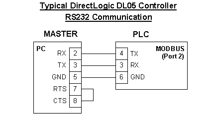
Here’s a typical example of a PC connected directly to a PLC Direct DL05.
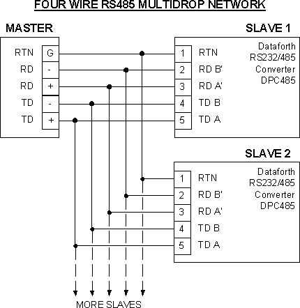
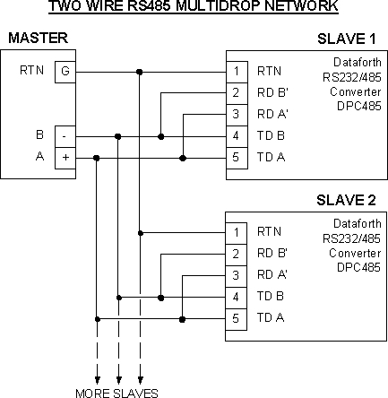
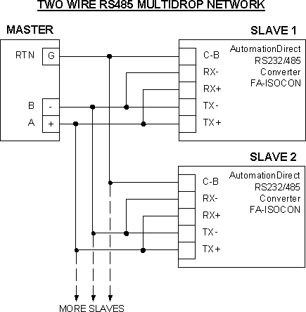
RS485 connections can be wired in a 2- wire or 4-wire arrangement. It is preferable to use the 2-wire multidrop network. The change can typically be made between both by use of two jumpers. The diagrams below show the wiring connections for the Dataforth and AutomationDirect RS485 to RS232 connectors.
Dataforth Converters
AutomationDirect (Facts) Converters

References:
AutomationDirect FA-ISOCON manual: http://www.facts-eng.com/manuals/faisoconm.pdf
RS-485 connection example see Dataforth Application Note AN202 http://www.dataforth.com/catalog/pdf/an202.pdf
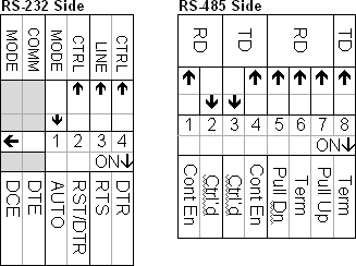
12a. What are the dip switch settings for the Dataforth DPC485?
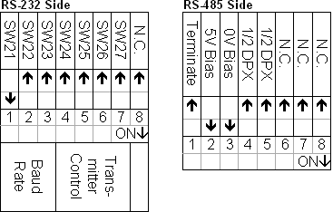
12b. What are the dip switch settings for the AutomationDirect (Facts Engineering) FA-ISOCON?
13. Will I damage something if I get the wires swapped?
No, the RS-232/422/485 standards are designed to withstand short circuits and swapped wires. Damage may occur if a voltage greater than 25 volts is placed on one of the lines.
14. Do I have to turn off the PLC and other devices to connect the wires?
This is the only recommended safe way to install wiring.
15. How far away can devices be away from each other?
For an RS-232 connection the maximum distance is 15 meters.
For RS-422 and RS485 connections the maximum distance is 4000 meters.
Repeaters can be used to increase the distance.
16. What sort of cable should I use?
A shielded #18AWG cable with twisted pairs is recommended. The shield should be grounded on one end only.
Communicating
17. What are the communication settings?
This is unique to each device. Consult the manufacturer’s manual. A typical setup has
|
Baud Rate: |
9600 |
|
Parity: |
Even |
|
Data Bits: |
8 |
|
Stop Bits: |
1 |
18. What are ASCII Chart ">ASCII and RTU modes?
ASCII (American Standard Code for Information Interchange) uses 10 bits of data comprised of 7 data bits, 1 parity bit, 1 start bit and 1 stop bit. It uses LRC (Longitudinal Redundancy Check) for error checking. The advantage of ASCII is it allows up to 1 second time intervals to occur between character transmissions without generating an error. It's most useful when communication is slow.
RTU mode (Remote Terminal Unit) contains 4 bit hex characters divided up into 8 data bits, 1 parity bit, 1 start bit, and 1 stop bit. It uses http://en.wikipedia.org/wiki/Cyclic_redundancy_check for more detailed information.">CRC (Cyclical Redundancy Check) for error checking. RTU has the advantage that it can send more data in the same amount of time but it has to be in a continuous stream (no delays between characters).
19. OK, that was too much information for me. Should I use RTU or ASCII?
RTU is the most commonly used.
Addressing
20. Where do I find information on identifying the addresses?
This is unique to each device. Consult the manufacturer’s manual.
21. What is a coil?
This is a single bit of information indicating either an ON (1) or OFF (0) state. Types of coils include valve states, alarms/warnings and status.
22. What is a register?
This is a 16-bit data field. The data can be in binary (decimal), hex or BCD format. Types of register data include temperatures, pressures, times and PID variables.
23. Why do some addresses have only four digits when I expect five?
Typically there are two ways that MODBUS can address the PLC:
#1 - Most software packages allow you to specify the MODBUS data type and address. This is the easiest method and most often used.
#2 - If your host software package specifies an address only then you will need to determine the addressing mode as either 484 or 584/984. If the address is supposed to be four digits then it is 484 mode. If the address is to be five digits then it is 584/984 mode. The following table shows what will need to be added to the existing address:
|
|
484 mode |
584/984 mode |
|
Coils |
+ 1 |
+ 1 |
|
Registers |
+ 4001 |
+ 40001 |
24. Why is the addressing off by one?
Some Modbus master devices compute register locations differently so the actual address might be shifted by one. This is often referred to as “adding the offset”.
25. Can I write a value to the PLC?
Yes there are both read and write functions.
26. Can I control the PLC remotely through MODBUS?
Only if the PLC program is programmed to do it.
Troubleshooting
27. How can I test the MODBUS connection?
The best way to do this is to have a separate computer/laptop with the ability to monitor MODBUS by acting as a Master station.
Vendors that have stand alone MODBUS testing software include:
- Ocean Controls - http://www.oceancontrols.com.au/modbus/modview.htm
- Wintech Software - http://www.win-tech.com/html/modbus1.htm
- LabVIEW can be used but the MODBUS component called BusVIEW must be purchased first from SEG Corp. (www.softwarewithrelish.com).
The only cable required to test MODBUS is a three conductor, wired to one end with a standard 9 pin connector for the computer com port and the other end loose to tie into the customer interface terminalsThe 9 pin terminal 2 is Rx, terminal 3 is Tx, and 5 is GND (or Common). So the Rx on one end goes to the Tx on the other and vice versa, and the GND goes to GND.
To test an RS485 connection first establish that the RS232 side is working by disconnecting the RS232/485 converter and testing by the above method. Once the RS232 side is confirmed as working the only way to verify the RS485 connection with a PC is to use another RS232/485 converter to convert the signal back into a RS232 signal that the PC can read. A converter on another PLC can be used for testing but the RS232 side of the converter must be disconnected first before using the PC.
28. I’m getting communication time out errors and I can’t get the device to communicate with my software? What could be wrong?
- Transmit and receive signals can often be verified by watching the transmit and receive lights on the Modbus components.
- The communication parameters are not set up correctly on the device. Check the settings match for slave address, baud rate, stop bit and parity.
- Make sure the host software has the same configuration
- The transmit and receive wires are crossed. Try switching the wires as it will not cause any damage.
- Check the conductivity on each wire for loose connections or broken wires.
- High power lines or improper grounding is causing noise in the system. Are the communication cables shielded and is the shield grounded on one end.
29. The MODBUS data does not match what is on the screen. What is wrong?
- The addressing may be off by one depending upon how the host software handles addressing.
- Slow communications may delay updates on MODBUS data.
- Host software is not configured to continually poll for new readings.
- The data format may be set up incorrectly. Refer to the user manual’s MODBUS table for the data formatting.
- Typically the data will be in binary/decimal format. In certain situations the data may be in hexadecimal.
- Some data has implied decimal places so that a value of 432.1 will be 4321 in MODBUS.
- Some large numbers may require two addresses. This is called a double word. The low address (word) will contain the first four places while the higher address (word) will contain the upper four digits. For a quick conversion take the (high word X 10000) + low word.
- Sometimes scaling is required to derive the proper number. The scaling is indicated on the MODBUS table where the actual data is given and then the scale value. For example, if the actual reading is from 0 to 4095 and the scaling is from 0 to 100 then the actual value will have to be divided by 40.95 to get the proper scaling.