Siemens SIMATIC Step 7 Programmer's Handbook
This handbook is a collection of programming overviews, notes, helps, cheat sheets and whatever that can help you (and me) program a Siemens PLC.
If you have experience with Siemens then please contribute.
Siemens Website Quick Links
This is a listing of tutorials and manuals found on the Siemens automation website that will get you started on the SIMATIC Step 7 software for S7-300 and S7-400 systems. From a new users perspective I’ve only heard disparaging comments about finding the right information on the Siemens’ website. I have to agree. Its information overload at it’s best. There’s a lot of different stuff there thrown together and found in different spots with very long URL addresses to add to the confusion.
Have no fear. We’re here to help. So we’ll look at the essentials for your journey.
- The software if you haven’t got it yet
- Getting a sense for the product line
- Where to start with the manuals
- Online training material
- Downloadable Flash tutorials
Of course the best type of training is the hands on type but if that’s not an option then you’ll need to start digging in.
Who’s got the Software?
If you are just learning and can’t easily get the software then there are two options.
- Order the demo CD which will give you a free 30-day trial period.
- Download a free working copy of Step 7 Lite. There are differences between the regular version of Step 7 and Step 7 Lite but for learning purposes you can go along way with the free Lite version.
First Things First
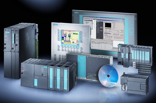
The first thing I like to do with a new product is get an overview of everything. Getting used to part numbers and product groupings can go a long way with your comfort level. The best thing for this is the sales catalog (ST 70 – 2005). You can also order a hard copy.
Where to Start? Manuals, manuals, everywhere!
Once you install the Step 7 software there will be a directory under the SIMATIC folder called Documentation that includes the most important manuals. Hard copies can be ordered with number 6ES7810-4CA08-8BW1. Here’s how I would digest them.
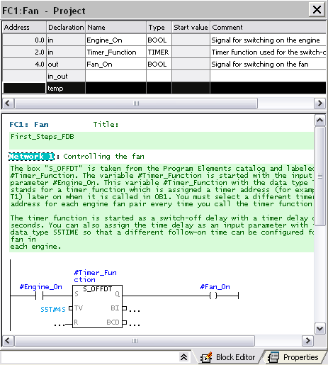
- Working with STEP 7 - This is a basic introduction to Step 7 which walks through an example of controlling engines. While it’s not the complete picture it does ease you very well into the learning curve of the Step 7 software.
- Programming with STEP 7 Manual - Here’s the fuller manual for the programming interface which is also the same as the online help accessed by pressed the F1 key.
- Configuring Hardware and Communication Connections STEP 7 Manual - Everything to do with the Hardware Configurator.
- Statement List, Ladder Logic, and Function Block Diagram Reference Manuals - These manuals contain both the user’s guide and the reference description of the programming language or representation type. You only require one language type for programming an S7-300/S7-400, but you can mix the languages within a project, if required. If you’re more comfortable with Ladder Logic or Function Block Diagram then start there but sooner or later you’ll have to become familiar with Statement List.
- System Software for S7-300 and S7-400 System and Standard Functions Reference Manual - The S7 CPUs have integrated system functions and organization blocks included with their operating system, which you can use when programming. This manual provides you with an overview of the system functions, organization blocks, and loadable standard functions available in S7, and detailed interface descriptions for their use in your programs.
Training Material
There’s gold in that website if you just do a little digging! If you’re having a tough go with the manuals then you should definitely download the training material. There’s a lot more screen shots and even a picture of a balding pudgy guy to point things out to you. What more could you want?
Flash Tutorials
If you’re not the manual type (and even if you are) check out the Siemens Step 7 Flash tutorials. These are very professionally done with a nice sounding narrator to take you through all the basics of the Step 7 software and hardware.
What's Next?
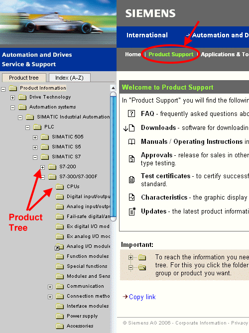
Of all the starting places to dig for more info I find the support section the best especially if you have a part number or key word you can search on. Clicking on the Product Support link will bring up a tree on the left hand side that can be expanded down to the product of your affection. Good luck and happy hunting.
Review of Siemens SIMATIC Step 7 Lite Programming Software
“Great taste. Less filling.â€

When one hears the words “Lite†and software you tend to think of software that’s not really usable. Depending on your needs this may not be the case with the Siemens STEP 7 Lite package. The four major limitations in STEP 7 Lite verses the more advanced STEP 7 package are:
- Support limited to the SIMATIC S7-300 PLC, the C7 all-in-one PLC and HMI, and the intelligent CPUs of the ET200 distributed I/O family. So no programming for the S7-200 or S7-400 PLC series.
- No networking whatsoever. Remote I/O racks (IM modules) are supported but there’s nothing for Profibus DP even if you have a DP port on your CPU.
- No support for multi-projects or HMI integration.
- No communication processors (CP) or function modules (FM) supported.
If you’re interested in more details then refer to our chart of differences between the Step 7 program packages. So there are quite a few major limitations with the Step 7 Lite software which may end your further reading of this review.
On the other hand, the current availability of a free download of the SIMATIC Step 7 Lite software makes it awfully tempting to take a look at it. If your only use of Siemens PLCs are an S7-300, C7 or ET200 in a stand alone application with no special needs (CP or FM) then I could highly recommend the Lite package. It has the same level of programming functionality as the regular Step 7 packages plus some nifty interface enhancements to make it easier on the eyes and on the brain. It is possible (though not easy) to convert any software created in the STEP 7 Lite to STEP 7 and visa versa keeping in mind the limitations of the Lite version. Since the packages bear a lot of similarities it will also be easy for the student to transfer any learning on the Lite package over to STEP 7.
First Impressions
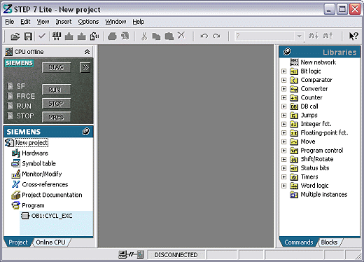
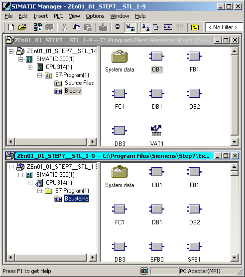
For a user of the regular STEP 7 software the first thing to notice is there is no SIMATIC Manager. That’s because the Lite version doesn’t support multi-projects or networking. The STEP 7 Lite software opens right up to the editor screen.
The overall aim of the Lite package was to make the interface easier for new users. I think they’ve done that while making it friendlier for everyone involved. The added graphics and color are a welcome addition. Another nice friendly feature is the extended hover help on the menus and icons where clicking on the tool tip expands it into more help text. On that note all the pop up dialogs are clearer then its STEP 7 counterpart.
One of the major differences can be seen on the left hand side window. Pretty much everything the programmer needs for maintaining the project is neatly organized here. There’s even a convenient thumb tack to pin it or make it automatically slide in and out when needed.
On the right hand side is the old familiar tree structure of commands and blocks. It’s missing the quick little reference help window on the bottom which has been replaced by just hovering your mouse over the command to get a fuller title (the F1 key works just the same too). The FC and FB blocks have been moved from here to a more logical place in the project window on the left hand side.
The Left Side Bar – CPU Overview and Project Window

The top portion introduces a CPU box with easy access to controls, diagnostics (Ctrl+D) and setup of the CPU. That’s not something I feel is necessary to be there all the time so I minimized it. Too bad there’s no apparent way to just get rid of it all together.
The Project Window below it is great. Everything’s is here from hardware to documentation. Something that just thrilled me is the tabs below that separate the offline and online versions of the program. On the regular STEP 7 software there is often a confusion between when you are offline or online. STEP 7 Lite minimizes that confusion by also provided clearly differentiated color schemes for when you have a block open online. And if that wasn’t all, the symbols beside the hardware and each block instantly tell you of differences between the offline and online versions of your program. You can just hover the mouse over the symbol to get more detail.
It’s also nice to have all the blocks clearly color coded and nicely arranged. You can drag and drop then anywhere in the list. There’s even a new feature of “Category†which is simply an organizational label inserted between blocks. In this screen I’ve inserted the category “Engine Data†and “Special Dataâ€. This could be really helpful for logically grouping blocks in larger projects.
I also like the new way of creating blocks. From the pull down menu select Insert | Block … and this nifty dialog box pops up with all the selections on it. Even the OB selection has a nice drop down box of all the OBs available with its symbolic name.
The Hardware Manager
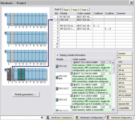
The greatest change of all is the overhauled hardware manager. The layout is great and is to be expected without the need to factor in networking. Just drag and drop your hardware on the picture and away you go. There’s even a nice hardware comparison feature clearly showing any differences between the offline and online setups.
The Editor
Much of the editor is like its big sister STEP 7. One noticeable part that’s “missing in action†is the detail view that gives quick access to info, cross reference, address info, etc. One part I like is a slight revamp of the declaration table. Instead of the tree like structure it’s one simple table with a column indicating its declaration. That means no having to dig through the tree just to see all the declaration variables.
Conclusion
Other then what we’ve all ready listed there are no other major differences. The symbol table, monitor/modify (a.k.a. VAT), and the reference data are all very similar to STEP 7. Overall, if you can live with the limitations, the STEP 7 Lite version is a great little package. Hopefully some of the better implementations will find there way into the STEP 7 software.
P.S. One little caveat is that it kept crashing on my plenty beefy enough Windows XP Home computer. Save often, arrgh!
Step 7 Connecting, Downloading and Uploading
These are general guidelines for connecting, downloading and uploading from an S7-300 or S7-400 PLC. The following procedures were created using Siemens SIMATIC STEP 7 version 5.4 software.
To start, open the SIMATIC Manager.
Now follow the links below.
Connecting to the S7 PLC
The Programming Cables
There are three major types of programming cables:
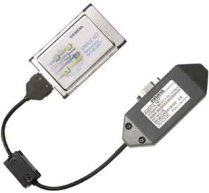
1. The CP5512 card in a PCMCIA slot.
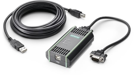
2. The PC Adapter using a serial or USB connection
3. An Ethernet cable

The CP5512 card and the PC Adapter can communicate on either an MPI or PROFIBUS port. Note that PROFIBUS is labeled as DP on the Siemens connection ports. These cables can piggyback on existing connectors. Be aware that the PC Adapter draws its power to work from the connection port so check the power LED for proper operation. The CP5512 card draws its power from the computer.
For Ethernet (TCP/IP) use a standard Ethernet cable from the computer to a CPU with an Ethernet port, a CP 343/443 module or a network switch all ready attached to the PLC network.
Checking Communications
With the programming cable plugged in, you can check for proper operation by clicking on the Accessible Nodes icon.
![]()
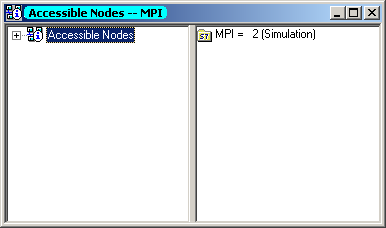
If communications are successful, you'll see a window pop up similar to the one below. If so, then close the Accessible Nodes window and proceed to the download or upload section.
If communication fails then you will receive a message like below.
This indicates that the cable is not in the right computer port or the cable is not plugged in properly.
Setting the PG/PC Interface
In order to start communication to the PLC you will need to match the "PG Interface" setting with the programming cable and protocol. To do this, select the menu Options > Set PG/PC Interface.

The following dialog box will open up displaying all the different interfaces (i.e. communication drivers).
Each cable has its own interface. For Ethernet select the TCP/IP interface for your computers network card. Be careful not to select your wireless Ethernet connection.
To get it working quickly it is best to select the interface with the Auto designation. This will discover working settings and use them automatically.
For the PC Adapter click on the Properties button and make sure the Station Parameters Address is a unique network address. It should not conflict with existing PLC and slave devices on the network. Also, check under the Local Connection tab and make sure connection selection matches the port the cable is connected into.
Once the proper interface is selected and the properties are set then click OK and use the Accessible Nodes window to check for successful communications. It should work. If not double-check the connection and cable. With the CP5512 and PC Adapter cables, you should use the MPI port, as this is the default connection for Siemens.
If this doesn't work then I don't know what to tell you.
Downloading
First, in order to enable the download menu commands, you must select the Block folder in the project's station you wish to download.
There are three methods of downloading.
- Partial download of selected blocks
- Full download of all blocks and system data
- Complete deletion of online PLC blocks and then downloading of all blocks and system data
Partial Download
Partial downloads are used in existing projects where only one or more blocks will be downloaded. To perform this type of download select the block(s) you wish to download and then select the PLC > Download menu item or the download button ![]() .
.
Holding down the Ctrl key or the Shift key allows more then one block to be selected at a time. Be careful though as the order of download will occur in the order that the blocks were selected. This may mean that an error will occur if a block is called before it is downloaded.
The CPU will need to be in Stop mode before downloading the System Data Block (SDB) as this is equivalent to a hardware configuration download. This is usually not necessary in a PLC that has all ready had its hardware configured. If you do download the system data, the following messages will prompt you through the transitions.
If the CPU is in Run mode then you will be prompted to Stop the CPU. The software will do the Run to Stop transition when you click OK.
After downloading the SDB you will be prompted to Run the CPU again.
Clicking Yes will automatically put the CPU back into run mode.
Full Download
To download all the blocks at once make sure you are in the Block folder and select the Edit > Select All menu item. Click on the Download icon ![]() . You will be prompted to overwrite any existing blocks and if you want to load the system data (see above).
. You will be prompted to overwrite any existing blocks and if you want to load the system data (see above).
Clearing the CPU Memory and then Downloading
The partial and full download methods above will overwrite existing blocks but will not any blocks from memory. In order to completely delete the existing program in the CPU and download a new project select the Blocks folder and then use the PLC > Download User Program to Memory Card menu item.
The following dialog box will pop up prompting you about the deletion of all the blocks and project data in the PLC. Click Yes to perform the operation.
After this, follow the normal download procedure.
Uploading
There are two methods for uploading. The first is when you have the original project and you want to preserve the symbols and comments. The second method, when you don't have the original project, will upload everything from the CPU but will have no associated documentation (i.e. symbols and comments).
Uploading to an Existing Project
With the existing project open, select the View > Online menu item.
This is the same as the Online button on the icon bar.
![]()
This will open up another window called the Online Partner. It shows the existing blocks inside the CPU. The Online version is indicated by the highlighted title bar.
There is a connection between these two versions so that uploading from the online partner makes sure to preserve all the symbols and comments. Be careful. After uploading, make sure to close the online partner and do all work from the offline version.
To upload individual blocks, select them in the Online view and choose the PLC > Upload to PG menu item. For a full upload, select the Block folder and do the same.
Upload without an Existing Project
Follow these steps when you do not have the original project but wish to upload the program for backup purposes. With an existing project open or a new blank project select the PLC > Upload Station to PG… menu selection.
In the next screen, fill in the slot the CPU is in (this is always 2 for S7-300) and the node address of the communication port on the CPU. In the case below we are talking to a CPU over MPI with node address 10.
After clicking OK, the whole contents of the PLC including all blocks and hardware configuration will be uploaded into a new station in the project.
While this project contains no documentation, it can be used as a backup to download later if needed.
Step 7 Lite, Step 7 and Step 7 Professional Differences
STEP 7 Lite |
STEP 7 |
STEP 7 Professional |
|
| Configuring | |||
| PLCs |
S7-300/C7 |
S7-300/S7-400/C7/WinAC |
|
| Modules |
Digital, analog I/O, IFM |
Digital, analog I/O, IFM, FM, CP |
|
| Networking/communications |
No |
Time-driven, cyclic data transmission between automation components; |
|
| Distributed I/O |
No |
Yes |
|
| Alarm configuring (display->HMI) |
No |
Yes |
|
| Write/read to/from MMC |
Yes, in CPU only |
Yes, in CPU and direct on PG/PC |
|
| Export/import |
Program, symbols |
Program, symbols, hardware configuration |
|
| Documentation function |
Included |
Included - S7-DOCPRO option for standard-compliant documentation of the S7 project |
|
| Multi-language documentation of projects |
Yes |
Yes |
|
| Multi-user engineering |
No |
Yes |
|
| Programming | |||
| Languages |
LAD/FBD/STL |
LAD/FBD/STL and STL sources |
As Step 7 |
| Structured/symbolic programming |
Yes/Yes |
Yes/Yes |
|
| Check/establish program consistency |
Yes/Yes |
Yes/Yes |
|
| Standard libraries/user libraries |
Yes/No |
Yes/Yes |
|
| Online functions | |||
| Online access |
MPI |
MPI, Profibus, Option: Industrial Ethernet |
|
| Test functions |
Monitor, control, force |
Monitor, control, force, single step (debug) |
|
| Comparison function offline/online |
Program, hardware configuration |
Program |
|
| Diagnostics |
System diagnostics |
System diagnostics, report system fault, integrated process fault diagnostics in S7-Graph |
|
| Optional packages | |||
| Optional programming languages |
None |
S7-Graph, S7-SCL, S7-HiGraph, CFC |
S7-HiGraph, CFC |
| Options for simulation, documentation, diagnostics and remote maintenance |
S7-PLCSIM, S7-Teleservice |
S7-PLCSIM, S7-Teleservice, S7-DOCPRO, S7-Pdiag |
S7-Teleservice, S7-DOCPRO, S7-Pdiag |
The Case of the Missing SIMATIC Step 7 Documentation
“We had documentation at one time.”
Sound familiar? Have you suddenly found changes that have been made in the PLC but not in the offline program? Nobody knows what happened.
Unfortunately this is an all too common phenomena with the Siemens SIMATIC Step 7 software. The problems stem from the flexibility of the software both for downloading and editing the online program. If the person is not familiar with the software it’s very easy to get confused if the changes are being made on the computer or in the controller.
How to solve this problem? Let’s first of all review some basic terminology. After that is a step by step best practice when editing programs. Finally, we’ll highlight the pitfalls and the indicators that tell you whether you are offline or online. This procedure applies to SIMATIC Step 7 version 5.4.
Terminology
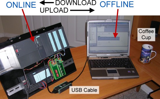
Offline program – The program that is stored on the hard disk of the computer. This will contain the documentation. It’s very important to keep a pristine copy of the offline program as the associated documentation is not stored in the PLC.
Online program – This is the program resident in the PLC.
Download – The act of taking the offline program on the computer and downloading it into the PLC.
Upload – Taking the program in the PLC and bringing it up to the computer. Doing this without having the associated offline program open will cause a loss of documentation.
Save – Stores the open block onto the hard drive. It’s important to realize that an edited block can be downloaded to the PLC without saving it offline. Note that this only saves the opened block and not any others that are concurrently open.
These may seem like simple terms but it’s important to understand how they’re used in the Siemens environment.
Here are some other terms that may come up.
PG/PC – This is Siemens way of referring to a PC or laptop running the SIMATIC software.
Nodes – Refers to any programmable device (in our case a PLC) in the network which will have its own unique address.
Best Practice
The best practice is to make sure you are working from an offline file. There really isn’t any reason to be working on the program inside the PLC. Of course, this assumes that you have a good working copy to begin with. The “golden” copy of the program should live somewhere on a network server or have a dedicated place on one computer or laptop. I’ve even heard of some companies using USB memory sticks to store the latest and greatest which is great but an original copy should still live on a computer that is backed up.
- Open the offline file from the File pull down menu and select Open or use the Open Project icon
 on the toolbar. In the dialog box select the project under the User Project tab. Click OK. You may have to select Browse to find it in the directory structure. Note if the Manager was closed with a project open then it will open back up to that project automatically.
 - Expand the project tree down to the program files and select the Blocks folder. Good practice dictates that all blocks should be opened from here.
- Once changes have been made:
- Save the block to the hard disk by clicking the Save icon
 (or menu item File | Save)
 - Download the block by clicking the Download icon
 (or menu item PLC | Download). If the block all ready exists in the PLC then it will confirm that you want to overwrite it1. Click Yes.
 - Note that downloading from here only sends that one block to the PLC. It does not download the entire program.
- To monitor the block make sure to open it using steps 1 through 3 and then press the Monitor icon
 (or menu item Debug | Monitor). The window’s title bar will highlight a lovely shade of blue to indicate a connection to the CPU. It’s important to note here that you are still working with the program on the computer and not the PLC. If the procedure in step 3 has not been followed then discrepancies can occur between what you are monitoring in the PLC and what is displayed in the SIMATIC software.
That’s it. Following these simple steps will save a lot of headaches.

The Pitfalls and Warning Signs
So where do some people get lost? Here are some common mistakes and their warning signs. If you get any of these dialog boxes then you should really back out and start over because you’re on the road to losing your documentation.
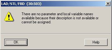
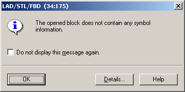
The result of opening the block looks like this
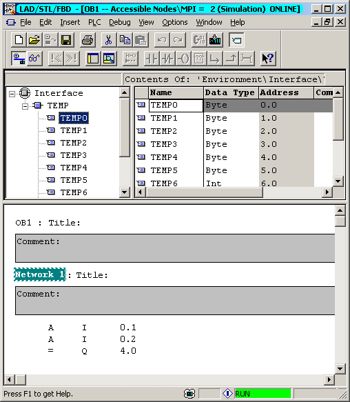
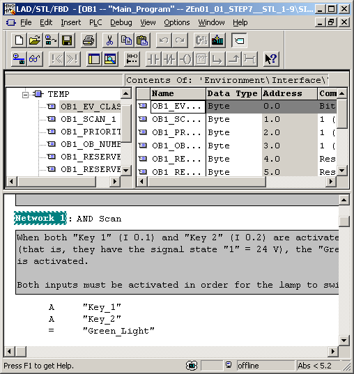
This is an example void of documentation. Notice the local parameters all say TEMP. There are no comments or titles. There are no symbols so it’s all in direct addressing. The properly documented copy looks like this...
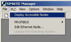
Pitfall #1 – Using Accessible Nodes to Open Blocks
The Display Accessible Nodes ![]() selection under the PLC menu is a handy way to see what is connected to the network but it should never be used to open blocks. Opening blocks from here uploads it straight from the PLC and produces the warnings dialog boxes shown above.
selection under the PLC menu is a handy way to see what is connected to the network but it should never be used to open blocks. Opening blocks from here uploads it straight from the PLC and produces the warnings dialog boxes shown above.
Pitfall #2 – Viewing Online from SIMATIC manager
Once a project is open and a connection to a PLC is established then selecting the Online button ![]() (menu View | Online) brings up a similar project tree showing the contents inside the PLC. The window title bar is highlighted in blue to indicate its online status. Working from this window presents less of a danger for losing documentation but it is confusing and could lead to problems. For instance if a block is renamed offline and then the old one is opened online then it will have no associated documentation.
(menu View | Online) brings up a similar project tree showing the contents inside the PLC. The window title bar is highlighted in blue to indicate its online status. Working from this window presents less of a danger for losing documentation but it is confusing and could lead to problems. For instance if a block is renamed offline and then the old one is opened online then it will have no associated documentation.
The proper way to view a block online is to open the block and select the Establish Connection to Configured CPU icon ![]() . Just make sure what you are viewing has been downloaded to the PLC.
. Just make sure what you are viewing has been downloaded to the PLC.
Pitfall #3 – Opening the Online Partner
If an offline block is open then selecting the Open Offline/Online Partner icon ![]() (menu item File | Open Online) will switch it to the online version of the block for editing. Essentially this puts you in the same place as pitfall #2.
(menu item File | Open Online) will switch it to the online version of the block for editing. Essentially this puts you in the same place as pitfall #2.
Conclusion
Programming with SIMATIC Step 7 is different enough from other types of PLCs to throw off the casual user. Always working from the offline copy will make it less likely to screw up. Opening up a block from the accessible nodes window is always a no-no. Likewise, opening a block from a window that has a highlighted blue title bar will also cause potential problems. Be sure and read all dialog boxes especially the ones we’ve shown in the article. Avoid the pitfalls and keep that documentation. Mystery solved.
Footnote:
(1) Siemens dialog boxes have an option that says, “Do not display this message again.” This is handy for some annoying pop ups but it is really not a good idea to turn off important ones like warnings for overwriting blocks. These warnings are especially crucial if you are working on real machinery. If more then one person is using the software then you can reset these messages to display again by going to the SIMATIC Manager and select the menu Options | Customize. Click the General tab and press the Activate button. If it’s grayed out then all messages are set to display.
S7 Library Functions
I couldn't find a complete listing of all the function blocks in the standard Siemens S7 Libraries so I made one myself. It helps me get a better overview of what is available. The complete listing is also available as an Excel spreadsheet so you can sort or adjust to your needs.
System Function Blocks
| Number | Name | Family | Description |
| SFB 0 | CTU | IEC_TC | Count Up |
| SFB 1 | CTD | IEC_TC | Count Down |
| SFB 2 | CTUD | IEC_TC | Count Up/Down |
| SFB 3 | TP | IEC_TC | Generate a Pulse |
| SFB 4 | TON | IEC_TC | Generate an On Delay |
| SFB 5 | TOF | IEC_TC | Generate an Off Delay |
| SFB 8 | USEND | COM_FUNC | Uncoordinated Sending of Data |
| SFB 9 | URCV | COM_FUNC | Uncoordinated Receiving of Data |
| SFB 12 | BSEND | COM_FUNC | Sending Segmented Data |
| SFB 13 | BRCV | COM_FUNC | Receiving Segmented Data |
| SFB 14 | GET | COM_FUNC | Read Data from a Remote CPU |
| SFB 15 | PUT | COM_FUNC | Write Data to a Remote CPU |
| SFB 16 | COM_FUNC | Send Data to Printer | |
| SFB 19 | START | COM_FUNC | Initiate a Warm or Cold Restart on a Remote Device |
| SFB 20 | STOP | COM_FUNC | Changing a Remote Device to the STOP State |
| SFB 21 | RESUME | COM_FUNC | Initiate a Hot Restart on a Remote Device |
| SFB 22 | STATUS | COM_FUNC | Query the Status of a Remote Partner |
| SFB 23 | USTATUS | COM_FUNC | Receive the Status of a Remote Device |
| SFB 29 | HS_COUNT | COUNTERS | Counter (high-speed counter, integrated function) (only exist on the CPU 312 IFM and CPU 314 IFM) |
| SFB 30 | FREQ_MES | COUNTERS | Frequency Meter (frequency meter, integrated function (only exist on the CPU 312 IFM and CPU 314 IFM) |
| SFB 31 | NOTIFY_8P | COM_FUNC | Generating block related messages without acknowledgement indication |
| SFB 32 | DRUM | TIMERS | Implement a Sequencer |
| SFB 33 | ALARM | COM_FUNC | Generate Block-Related Messages with Acknowledgment Display |
| SFB 34 | ALARM_8 | COM_FUNC | Generate Block-Related Messages without Values for 8 Signals |
| SFB 35 | ALARM_8P | COM_FUNC | Generate Block-Related Messages with Values for 8 Signals |
| SFB 36 | NOTIFY | COM_FUNC | Generate Block-Related Messages without Acknowledgment Display |
| SFB 37 | AR_SEND | COM_FUNC | Send Archive Data |
| SFB 38 | HSC_A_B | COUNTERS | Counter A/B (integrated function) (only exist on the CPU 314 IFM) |
| SFB 39 | POS | ICONT | Position (integrated function) (only exist on the CPU 314 IFM) |
| SFB 41 | CONT_C | ICONT | Continuous Control (only exist on the CPU 314 IFM) |
| SFB 42 | CONT_S | ICONT | Step Control (only exist on the CPU 314 IFM) |
| SFB 43 | PULSEGEN | ICONT | Pulse Generation (only exist on the CPU 314 IFM) |
| SFB 44 | ANALOG | TEC_FUNC | Positioning with Analog Output (only exist on the S7-300C CPUs) |
| SFB 46 | DIGITAL | TEC_FUNC | Positioning with Digital Output (only exist on the S7-300C CPUs) |
| SFB 47 | COUNT | TEC_FUNC | Controlling the Counter (only exist on the S7-300C CPUs) |
| SFB 48 | FREQUENC | TEC_FUNC | Controlling the Frequency Measurement (only exist on the S7-300C CPUs) |
| SFB 49 | PULSE | TEC_FUNC | Controlling Pulse Width Modulation (only exist on the S7-300C CPUs) |
| SFB 52 | RDREC | DP | Reading a Data Record |
| SFB 53 | WRREC | DP | Writing a Data Record |
| SFB 54 | RALRM | DP | Receiving an Interrupt |
| SFB 60 | SEND_PTP | TEC_FUNC | Sending Data (ASCII, 3964(R)) (only exist on the S7-300C CPUs) |
| SFB 61 | RECV_PTP | TEC_FUNC | Receiving Data (ASCII, 3964(R)) (only exist on the S7-300C CPUs) |
| SFB 62 | RES_RECV | TEC_FUNC | Deleting the Receive Buffer (ASCII, 3964(R)) (only exist on the S7-300C CPUs) |
| SFB 63 | SEND_RK | TEC_FUNC | Sending Data (RK 512) (only exist on the S7-300C CPUs) |
| SFB 64 | FETCH_RK | TEC_FUNC | Fetching Data (RK 512) (only exist on the S7-300C CPUs) |
| SFB 65 | SERVE_RK | TEC_FUNC | Receiving and Providing Data (RK 512) (only exist on the S7-300C CPUs) |
| SFB 75 | SALRM | DP | Send interrupt to DP master |
| SFB 81 | RD_DPAR | IO_FUNCT | Read Predefined Parameter |
System Function Calls
| Number | Name | Family | Description |
| SFC 0 | SET_CLK | CLK_FUNC | Set System Clock |
| SFC 1 | READ_CLK | CLK_FUNC | Read System Clock |
| SFC 2 | SET_RTM | CLK_FUNC | Set Run-time Meter |
| SFC 3 | CTRL_RTM | CLK_FUNC | Start/Stop Run-time Meter |
| SFC 4 | READ_RTM | CLK_FUNC | Read Run-time Meter |
| SFC 5 | GADR_LGC | IO_FUNCT | Query Logical Address of a Channel |
| SFC 6 | RD_SINFO | DB_FUNCT | Read OB Start Information |
| SFC 7 | DP_PRAL | DP | Trigger a Hardware Interrupt on the DP Master |
| SFC 9 | EN_MSG | COM_FUNC | Enable Block-Related, Symbol-Related and Group Status Messages |
| SFC 10 | DIS_MSG | COM_FUNC | Disable Block-Related, Symbol-Related and Group Status Messages |
| SFC 11 | DPSYC_FR | DP | Synchronize Groups of DP Slaves |
| SFC 12 | D_ACT_DP | DP | Deactivation and activation of DP slaves |
| SFC 13 | DPNRM_DG | DIAGNSTC | Read Diagnostic Data of a DP Slave (Slave Diagnostics) |
| SFC 14 | DPRD_DAT | DP | Read Consistent Data of a Standard DP Slave |
| SFC 15 | DPWR_DAT | DP | Write Consistent Data to a DP Standard Slave |
| SFC 17 | ALARM_SQ | PMC_FUNC | Generate Acknowledgeable Block-Related Messages |
| SFC 18 | ALARM_S | PMC_FUNC | Generate Permanently Acknowledged Block-Related Messages |
| SFC 19 | ALARM_SC | PMC_FUNC | Query the Acknowledgment Status of the last ALARM_SQ Entering State Message |
| SFC 20 | BLKMOV | MOVE | Copy Variables |
| SFC 21 | FILL | MOVE | Initialize a Memory Area |
| SFC 22 | CREAT_DB | DB_FUNCT | Create Data Block |
| SFC 23 | DEL_DB | DB_FUNCT | Delete Data Block |
| SFC 24 | TEST_DB | DB_FUNCT | Test Data Block |
| SFC 25 | COMPRESS | DB_FUNCT | Compress the User Memory |
| SFC 26 | UPDAT_PI | IO_FUNCT | Update the Process Image Update Table |
| SFC 27 | UPDAT_PO | IO_FUNCT | Update the Process Image Output Table |
| SFC 28 | SET_TINT | PGM_CNTL | Set Time-of-Day Interrupt |
| SFC 29 | CAN_TINT | PGM_CNTL | Cancel Time-of-Day Interrupt |
| SFC 30 | ACT_TINT | PGM_CNTL | Activate Time-of-Day Interrupt |
| SFC 31 | QRY_TINT | PGM_CNTL | Query Time-of-Day Interrupt |
| SFC 32 | SRT_DINT | PGM_CNTL | Start Time-Delay Interrupt |
| SFC 33 | CAN_DINT | PGM_CNTL | Cancel Time-Delay Interrupt |
| SFC 34 | QRY_DINT | PGM_CNTL | Query Time-Delay Interrupt |
| SFC 35 | MP_ALM | PGM_CNTL | Trigger Multicomputing Interrupt |
| SFC 36 | MSK_FLT | DIAGNSTC | Mask Synchronous Errors |
| SFC 37 | DMSK_FLT | DIAGNSTC | Unmask Synchronous Errors |
| SFC 38 | READ_ERR | DIAGNSTC | Read Error Register |
| SFC 39 | DIS_IRT | IRT_FUNC | Disable New Interrupts and Asynchronous Errors |
| SFC 40 | EN_IRT | IRT_FUNC | Enable New Interrupts and Asynchronous Errors |
| SFC 41 | DIS_AIRT | IRT_FUNC | Delay Higher Priority Interrupts and Asynchronous Errors |
| SFC 42 | EN_AIRT | IRT_FUNC | Enable Higher Priority Interrupts and Asynchronous Errors |
| SFC 43 | RE_TRIGR | PGM_CNTL | Re-trigger Cycle Time Monitoring |
| SFC 44 | REPL_VAL | DIAGNSTC | Transfer Substitute Value to Accumulator 1 |
| SFC 46 | STP | PGM_CNTL | Change the CPU to STOP |
| SFC 47 | WAIT | PGM_CNTL | Delay Execution of the User Program |
| SFC 48 | SNC_RTCB | CLK_FUNC | Synchronize Slave Clocks |
| SFC 49 | LGC_GADR | IO_FUNCT | Query the Module Slot Belonging to a Logical Address |
| SFC 50 | RD_LGADR | IO_FUNCT | Query all Logical Addresses of a Module |
| SFC 51 | RDSYSST | DIAGNSTC | Read a System Status List or Partial List |
| SFC 52 | WR_USMSG | DIAGNSTC | Write a User-Defined Diagnostic Event to the Diagnostic Buffer |
| SFC 54 | RD_PARM | IO_FUNCT | Read Defined Parameters |
| SFC 55 | WR_PARM | IO_FUNCT | Write Dynamic Parameters |
| SFC 56 | WR_DPARM | IO_FUNCT | Write Default Parameters |
| SFC 57 | PARM_MOD | IO_FUNCT | Assign Parameters to a Module |
| SFC 58 | WR_REC | IO_FUNCT | Write a Data Record |
| SFC 59 | RD_REC | IO_FUNCT | Read a Data Record |
| SFC 60 | GD_SND | COM_FUNC | Send a GD Packet |
| SFC 61 | GD_RCV | COM_FUNC | Fetch a Received GD Packet |
| SFC 62 | CONTROL | COM_FUNC | Query the Status of a Connection Belonging to a Communication SFB Instance |
| SFC 63 | AB_CALL | PLASTICS | Assembly Code Block (only exists for CPU 614) |
| SFC 64 | TIME_TCK | CLK_FUNC | Read the System Time |
| SFC 65 | X_SEND | COM_FUNC | Send Data to a Communication Partner outside the Local S7 Station |
| SFC 66 | X_RCV | COM_FUNC | Receive Data from a Communication Partner outside the Local S7 Station |
| SFC 67 | X_GET | COM_FUNC | Read Data from a Communication Partner outside the Local S7 Station |
| SFC 68 | X_PUT | COM_FUNC | Write Data to a Communication Partner outside the Local S7 Station |
| SFC 69 | X_ABORT | COM_FUNC | Abort an Existing Connection to a Communication Partner outside the Local S7 Station |
| SFC 70 | GEO_LOG | IO_FUNCT | Determine Start Address of a Module |
| SFC 71 | LOG_GEO | IO_FUNCT | Determine the Slot Belonging to a Logical Address |
| SFC 72 | I_GET | COM_FUNC | Read Data from a Communication Partner within the Local S7 Station |
| SFC 73 | I_PUT | COM_FUNC | Write Data to a Communication Partner within the Local S7 Station |
| SFC 74 | I_ABORT | COM_FUNC | Abort an Existing Connection to a Communication Partner within the Local S7 Station |
| SFC 78 | OB_RT | DIAGNSTC | Determine OB program runtime |
| SFC 79 | SET | BIT_LOGC | Set a Range of Outputs |
| SFC 80 | RSET | BIT_LOGC | Reset a Range of Outputs |
| SFC 81 | UBLKMOV | MOVE | Uninterruptible Block Move |
| SFC 82 | CREA_DBL | DB_CTRL | Create a Data Block in the Load Memory |
| SFC 83 | READ_DBL | DB_CTRL | Read from a Data Block in Load Memory |
| SFC 84 | WRIT_DBL | DB_CTRL | Write from a Data Block in Load Memory |
| SFC 85 | CREA_DB | DB_FUNCT | Create a Data Block |
| SFC 87 | C_DIAG | COM_FUNC | Diagnosis of the Actual Connection Status |
| SFC 90 | H_CTRL | HF_FUNCT | Control Operation in H Systems |
| SFC 100 | SET_CLKS | CLK_FUNC | Setting the Time-of-Day and the TOD Status |
| SFC 101 | RTM | CLK_FUNC | Handling runtime meters |
| SFC 102 | RD_DPARA | IO_FUNCT | Redefined Parameters |
| SFC 103 | DP_TOPOL | DP | Identifying the bus topology in a DP master system |
| SFC 104 | CIR | PGM_CNTL | Controlling CiR |
| SFC 105 | READ_SI | PMC_FUNC | Reading Dynamic System Resources |
| SFC 106 | DEL_SI | PMC_FUNC | Deleting Dynamic System Resources |
| SFC 107 | ALARM_DQ | PMC_FUNC | Generating Always Acknowledgeable and Block-Related Messages |
| SFC 108 | ALARM_D | PMC_FUNC | Generating Always Acknowledgeable and Block-Related Messages |
| SFC 112 | PN_IN | PROFIne2 | Update inputs in the user program interface of PROFInet components |
| SFC 113 | PN_OUT | PROFIne2 | Update outputs in the user program interface of PROFInet components |
| SFC 114 | PN_DP | PROFIne2 | Update DP interconnections |
| SFC 126 | SYNC_PI | IO_FUNCT | Update process image partition input table in synchronous cycle |
| SFC 127 | SYNC_PO | IO_FUNCT | Update process image partition output table in synchronous cycle |
S5-S7 Converting Blocks
| Number | Name | Family | Description |
| FC 61 | GP_FPGP | S5_CNVRT | Change fixed point number to floating point number |
| FC 62 | GP_GPFP | S5_CNVRT | Change floating point number to fixed point number |
| FC 63 | GP_ADD | S5_CNVRT | Add floating point numbers |
| FC 64 | GP_SUB | S5_CNVRT | Subtract floating point numbers |
| FC 65 | GP_MUL | S5_CNVRT | Multiply floating point number |
| FC 66 | GP_DIV | S5_CNVRT | Divide floating point numbers |
| FC 67 | GP_VGL | S5_CNVRT | Compare floating point numbers |
| FC 68 | RAD_GP | S5_CNVRT | Extract root of floating point numbers |
| FC 69 | MLD_TG | S5_CNVRT | Clock generator |
| FC 70 | MLD_TGZ | S5_CNVRT | Clock generator (timing element) |
| FC 71 | MLD_EZW | S5_CNVRT | Message of first value with single flashing light, wordwise, A |
| FC 72 | MLD_EDW | S5_CNVRT | Message of first value with double flashing light, wordwise, A |
| FC 73 | MLD_SAMW | S5_CNVRT | Collected message, wordwise (sound alert) |
| FC 74 | MLD_SAM | S5_CNVRT | Collected message, bitwise |
| FC 75 | MLD_EZ | S5_CNVRT | Message of first value with single flashing light, bitwise, A |
| FC 78 | MLD_EDWK | S5_CNVRT | Message of first value with double flashing light, wordwise, A+M |
| FC 79 | MLD_EZK | S5_CNVRT | Message of first value with single flashing light, bitwise, A+M |
| FC 80 | MLD_EDK | S5_CNVRT | Message of first value with double flashing light, bitwise, A+M |
| FC 81 | COD_B4 | S5_CNVRT | Change BCD number to 16 bit dual number |
| FC 82 | COD_16 | S5_CNVRT | Change 16 bit dual number to BCD number |
| FC 83 | MUL_16 | S5_CNVRT | Multiply 16 bit dual numbers |
| FC 84 | DIV_16 | S5_CNVRT | Divide 16 bit dual numbers |
| FC 85 | ADD_32 | S5_CNVRT | Add 32 bit dual numbers |
| FC 86 | SUB_32 | S5_CNVRT | Subtract 32 bit dual numbers |
| FC 87 | MUL_32 | S5_CNVRT | Multiply 32 bit dual numbers |
| FC 88 | DIV_32 | S5_CNVRT | Divide 32 bit dual numbers |
| FC 89 | RAD_16 | S5_CNVRT | Extract roots of 16 bit dual numbers |
| FC 90 | REG_SCHB | S5_CNVRT | Bi-directional shift register, bitwise |
| FC 91 | REG_SCHW | S5_CNVRT | Bi-directional shift register, wordwise |
| FC 92 | REG_FIFO | S5_CNVRT | Buffer memory (FIFO) |
| FC 93 | REG_LIFO | S5_CNVRT | Stack register (LIFO) |
| FC 94 | DB_COPY1 | S5_CNVRT | Copy data block, direct assignment of parameters |
| FC 95 | DB_COPY2 | S5_CNVRT | Copy data block, indirect assignment of parameterization |
| FC 96 | RETTEN | S5_CNVRT | Save scratchpad memory |
| FC 97 | LADEN | S5_CNVRT | Load scratchpad memory |
| FC 98 | COD_B8 | S5_CNVRT | Change BCD number to 32 bit dual number |
| FC 99 | COD_32 | S5_CNVRT | Change 32 bit dual number to BCD number |
| FC 100 | AE_460_1 | S5_CNVRT | Read analog value |
| FC 101 | AE_460_2 | S5_CNVRT | Read analog value |
| FC 102 | AE_463_1 | S5_CNVRT | Read analog value |
| FC 103 | AE_463_2 | S5_CNVRT | Read analog value |
| FC 104 | AE_464_1 | S5_CNVRT | Read analog value |
| FC 105 | AE_464_2 | S5_CNVRT | Read analog value |
| FC 106 | AE_466_1 | S5_CNVRT | Read analog value |
| FC 107 | AE_466_2 | S5_CNVRT | Read analog value |
| FC 108 | RLG_AA1 | S5_CNVRT | Output analog value |
| FC 109 | RLG_AA2 | S5_CNVRT | Output analog value |
| FC 110 | PER_ET1 | S5_CNVRT | Read and Write for extended periphery (direct assignment of parameters) |
| FC 111 | PER_ET2 | S5_CNVRT | Read and Write for extended periphery (indirect assignment of parameters) |
| FC 112 | SINUS | S5_CNVRT | Sine (x) |
| FC 113 | COSINUS | S5_CNVRT | Cosine (x) |
| FC 114 | TANGENS | S5_CNVRT | Tangent (x) |
| FC 115 | COTANG | S5_CNVRT | Cotangent (x) |
| FC 116 | ARCSIN | S5_CNVRT | Arc sine (x) |
| FC 117 | ARCCOS | S5_CNVRT | Arc cosine (x) |
| FC 118 | ARCTAN | S5_CNVRT | Arc tangent (x) |
| FC 119 | ARCCOT | S5_CNVRT | Arc cotangens (x) |
| FC 120 | LN_X | S5_CNVRT | Natural logarithm ln (x) |
| FC 121 | LG_X | S5_CNVRT | Decade logarithm Iog (x) |
| FC 122 | B_LOG_X | S5_CNVRT | General logarithm log (x) to basis b |
| FC 123 | E_H_N | S5_CNVRT | e to the power of n |
| FC 124 | ZEHN_H_N | S5_CNVRT | 10 to the power of n |
| FC 125 | A2_H_A1 | S5_CNVRT | AKKU 2 to the power of AKKU 1 |
IEC Function Blocks
| Number | Name | Family | Description |
| FC 1 | AD_DT_TM | IEC | Point Math Add duration to a time |
| FC 2 | CONCAT | IEC | Combine two STRING variables |
| FC 3 | D_TOD_DT | IEC | Combine DATE and TIME_OF_DAY to DT |
| FC 4 | DELETE | IEC | Delete in a STRING variable |
| FC 5 | DI_STRNG | IEC | Data type conversion DINT to STRING |
| FC 6 | DT_DATE | IEC | Extract the DATE from DT |
| FC 7 | DT_DAY | IEC | Extract the day of the week from DT |
| FC 8 | DT_TOD | IEC | Extract the TIME_OF_DAY from DT |
| FC 9 | EQ_DT | IEC | Compare DT for equal |
| FC 10 | EQ_STRNG | IEC | Compare STRING for equal |
| FC 11 | FIND | IEC | Find in a STRING variable |
| FC 12 | GE_DT | IEC | Compare DT for greater than or equal |
| FC 13 | GE_STRNG | IEC | Compare STRING for greater than or equal |
| FC 14 | GT_DT | IEC | Compare DT for greater than |
| FC 15 | GT_STRNG | IEC | Compare STRING for greater than |
| FC 16 | I_STRNG | IEC | Data type conversion INT to STRING |
| FC 17 | INSERT | IEC | Insert in a STRING variable |
| FC 18 | LE_DT | IEC | Compare DT for smaller than or equal |
| FC 19 | LE_STRNG | IEC | Compare STRING for smaller than or equal |
| FC 20 | LEFT | IEC | Left part of a STRING variable |
| FC 21 | LEN | IEC | Length of a STRING variable |
| FC 22 | LIMIT | IEC | Point Math Limit |
| FC 23 | LT_DT | IEC | Compare DT for smaller than |
| FC 24 | LT_STRNG | IEC | Compare STRING for smaller than |
| FC 25 | MAX | IEC | Point Math Select maximum |
| FC 26 | MID | IEC | Middle part of a STRING variable |
| FC 27 | MIN | IEC | Point Math Select minimum |
| FC 28 | NE_DT | IEC | Compare DT for unequal |
| FC 29 | NE_STRNG | IEC | Compare STRING for unequal |
| FC 30 | R_STRNG | IEC | Data type conversion REAL to STRING |
| FC 31 | REPLACE | IEC | Replace in a STRING variable |
| FC 32 | RIGHT | IEC | Right part of a STRING variable |
| FC 33 | S5TI_TIM | IEC | Data type conversion S5TIME to TIME |
| FC 34 | SB_DT_DT | IEC | Point Math Subtract two time values |
| FC 35 | SB_DT_TM | IEC | Point Math Subtract duration from a time |
| FC 36 | SEL | IEC | Point Math Binary selection |
| FC 37 | STRNG_DI | IEC | Data type conversion STRING to DINT |
| FC 38 | STRNG_I | IEC | Data type conversion STRING to INT |
| FC 39 | STRNG_R | IEC | Data type conversion STRING to REAL |
| FC 40 | TIM_S5TI | IEC | Data type conversion TIME to S5TIME |
PID Control Blocks
| Number | Name | Family | Description |
| FB 41 | CONT_C | ICONT | Continuous Control |
| FB 42 | CONT_S | ICONT | Step Control |
| FB 43 | PULSEGEN | ICONT | Pulse Generation |
| FB 58 | TCONT_CP | CONTROL | Temperature Continuous Controller |
| FB 59 | TCONT_S | CONTROL | Temperature Step Controller |
Communication Blocks
| Number | Name | Family | Description |
| FB 2 | IDENTIFY | CP_300 | For checking device properties |
| FB 3 | READ | CP_300 | Reads data from a data area of the communication partner specified by a name or index depending on the assignment of parameters for the job. |
| FB 4 | REPORT | CP_300 | Allows unconfirmed transmission of variables by an FMS server. |
| FB 5 | STATUS | CP_300 | allows status information to be requested from the communications partner on the specified FMS connection. |
| FB 6 | WRITE | CP_300 | Transfers data from a specified local data area to a data area on the communication partner. |
| FB 8 | USEND | CP_300 | Uncoordinated Sending of Data |
| FB 9 | URCV | CP_300 | Uncoordinated Receiving of Data |
| FB 12 | BSEND | CP_300 | Sending Segmented Data |
| FB 13 | BRCV | CP_300 | Receiving Segmented Data |
| FB 14 | GET | CP_300 | Read Data from a Remote CPU |
| FB 15 | PUT | CP_300 | Write Data to a Remote CPU |
| FB 20 | GETIO | IO_FUNCT | Read All Inputs of a DP Standard Slave/PROFINET IO Device |
| FB 21 | SETIO | IO_FUNCT | Write All Outputs of a DP Standard Slave/PROFINET IO Device |
| FB 22 | GETIO_PART | IO_FUNCT | Read a Part of the Inputs of a DP Standard Slave/PROFINET IO Device |
| FB 23 | SETIO_PART | IO_FUNCT | Write a Part of the Outputs of a DP Standard Slave/PROFINET IO Device |
| FB 55 | IP_CONFIG | CP_300 | Transfers a configuration data block (CONF_DB) containing connection data for an Ethernet CP. |
| FB 63 | TSEND | COMM | Sending Data via TCP native and ISO on TCP |
| FB 64 | TRCV | COMM | Receiving Data via TCP native and ISO on TCP |
| FB 65 | TCON | COMM | Establishing a Connection using TCP native and ISO on TCP |
| FB 66 | TDISCON | COMM | Terminating a Connection using TCP native and ISO on TCP |
| FB 67 | TUSEND | COMM | Sending Data via UDP |
| FB 68 | TURCV | COMM | Receiving Data via UDP |
| FC 1 | DP_SEND | CP_300 | transfers data to the PROFIBUS CP |
| FC 2 | DP_RECV | CP_300 | receives data on PROFIBUS |
| FC 3 | DP_DIAG | CP_300 | used to request diagnostic information |
| FC 4 | DP_CTRL | CP_300 | transfers control jobs to the PROFIBUS CP |
| FC 5 | AG_SEND | CP_300 | data by means of a configured connection to the communication partner (<= 240 bytes). |
| FC 6 | AG_RECV | CP_300 | data by means of a configured connection from the communication partner (<= 240 bytes, not email). |
| FC 7 | AG_LOCK | CP_300 | the external data access by means of FETCH/WRITE (not for UDP, email). |
| FC 8 | AG_UNLOCK | CP_300 | the external data access by means of FETCH/WRITE (not for UDP, email). |
| FC 10 | AG_CNTRL | CP_300 | allows you to diagnose connections. When necessary, you can reinitialize connection establishment using the FC. |
| FC 11 | PNIO_SEND | CP_300 | used for data transfer in the CP modes PROFINET IO controller or PROFINET IO device. |
| FC 12 | PNIO_RECV | CP_300 | used to receive data in the CP modes PROFINET IO controller or PROFINET IO device. |
| FC 40 | FTP_CONNECT | CP_300 | Establish an FTP connection |
| FC 41 | FTP_STORE | CP_300 | Store a file on the FTP server |
| FC 42 | FTP_RETRIEVE | CP_300 | Retrieve a file from the FTP server |
| FC 43 | FTP_DELETE | CP_300 | Delete a file on the FTP server |
| FC 44 | FTP_QUIT | CP_300 | Enable an FTP connection |
| FC 50 | AG_LSEND | CP_300 | data by means of a configured connection to the communication partner. |
| FC 60 | AG_LRECV | CP_300 | data by means of a configured connection from the communication partner (not email). |
| FC 62 | C_CNTRL | CP_300 | Query a connection status for S7-300 |
TI-S7 Converting Blocks
| Number | Name | Family | Description |
| FB 80 | LEAD_LAG | CONVERT | Lead/Lag Algorithm |
| FB 81 | DCAT | TIMERS | Discrete Control Alarm Timer |
| FB 82 | MCAT | TIMERS | Motor Control Alarm Timer |
| FB 83 | IMC | COMPARE | Index Matrix Compare |
| FB 84 | SMC | COMPARE | Scan Matrix Compare |
| FB 85 | DRUM | TIMERS | Event Maskable Drum |
| FB 86 | PACK | MOVE | Pack Data |
| FC 80 | TONR | TIMERS | Software Timer On Delay—Retentive |
| FC 81 | IBLKMOV | MOVE | Indirect Block Move |
| FC 82 | RSET | BIT_LOGC | Reset Range of Outputs |
| FC 83 | SET | BIT_LOGC | Set Range of Outputs |
| FC 84 | ATT | TABLE | Add to Table |
| FC 85 | FIFO | TABLE | First In/First Out Unload Table |
| FC 86 | TBL_FIND | TABLE | Table Find |
| FC 87 | LIFO | TABLE | Last In/First Out Unload Table |
| FC 88 | TBL | TABLE | Table |
| FC 89 | TBL_WRD | TABLE | Move Table to Word |
| FC 90 | WSR | SHIFT | Word Shift Register |
| FC 91 | WRD_TBL | TABLE | Word to Table |
| FC 92 | SHRB | SHIFT | Bit Shift Register |
| FC 93 | SEG | CONVERT | Seven Segment Decoder |
| FC 94 | ATH | CONVERT | ASCII to Hex |
| FC 95 | HTA | CONVERT | Hex to ASCII |
| FC 96 | ENCO | CONVERT | Encode Binary Position |
| FC 97 | DECO | CONVERT | Decode Binary Position |
| FC 98 | BCDCPL | CONVERT | Ten’s Complement |
| FC 99 | BITSUM | CONVERT | Sum Number of Bits |
| FC 100 | RSETI | BIT_LOGC | Reset Range of Immediate Outputs |
| FC 101 | SETI | BIT_LOGC | Set Range of Immediate Outputs |
| FC 102 | DEV | MATH_FP | Standard Deviation |
| FC 103 | CDT | TABLE | Correlated Data Table |
| FC 104 | TBL_TBL | TABLE | Table to Table |
| FC 105 | SCALE | CONVERT | Scaling Values |
| FC 106 | UNSCALE | CONVERT | Unscaling Values |
Miscellaneous Blocks
| Number | Name | Family | Description |
| FB 60 | SET_SW | TIMEFUNC | supports the summertime/wintertime changeover in CPUs that do not have the time status. For this purpose it sets the CPU clock to the current time and according to the changeover rules in the Control DB. |
| FB 61 | SET_SW_S | TIMEFUNC | supports the summertime/wintertime changeover in CPUs that do have the time status. For this purpose it sets the time status to the current time and according to the changeover rules in the Control DB. |
| FB 62 | TIMESTMP | TIMEFUNC | transfers the time-stamped messages of an IM153-2 into its instance DB. |
| FC 60 | LOC_TIME | TIMEFUNC | reads the time status or time of the CPU and calculates the local time. It is therefore only useful on CPUs with time status. |
| FC 61 | BT_LT | TIMEFUNC | calculates the local time from the base time given at the input. |
| FC 62 | LT_BT | TIMEFUNC | calculates the base time from the local time given at the input. |
| FC 63 | S_LTINT | TIMEFUNC | sets the required time interrupt to the preset time. This time is given in local time. |
Siemens Technical Terms
Otherwise known as Siemens speak. Here's a list of Siemens specific abbreviations and their meanings.
| Term | Description | Explanation |
| C7 | Combo PLC/HMI system | A PLC and screen in one package |
| CFC | Continuous Function Chart | Optional programming language |
| CP | Communication Processor | Modules used for special communication protocols |
| DB | Data Block | Memory storage areas for user data |
| FB | Function Block | A function with it's own data block |
| FBD | Function Block Diagram | Standard programming language |
| FC | Function Call | Called progammed blocks |
| FM | Function Module | Modules with special functions (e.g. positioning) |
| GSD | Generic Station Description | Files used for Profibus descriptions |
| HiGraph | Optional programming language | |
| IM | Interface Module | Modules to connect remote racks |
| LAD | Ladder Logic Diagram | Standard programming language |
| M7 | Programmable modules | A module with processing capabilities |
| MMC | Micro Memory Card | Compact plug-in memory card |
| MPI | Multi Point Interface | Standard communication protocol |
| OB | Organization Block | Blocks for user programs based on different operating system events. |
| OP | Operator Panel | Simple display with or without buttons |
| PCS | Process Control System | Software for the entire process chain |
| PG | Programming Terminal | Dedicated Siemens device - basically a PC |
| PPI | Point to Point Interface | Serial RS-232 communication |
| Profibus DP | Profibus Decentral Peripherals | Networking protocol used for factory automation |
| Profibus PA | Profibus Process Automation | Networking protocol used for process automation |
| S7 | SIMATIC Step 7 product line | |
| SCL | Structured Control Language | Optional programming language |
| SFB | System Function Block | Integrated FB for CPU information |
| SFC | System Function Call | Integrated FC for CPU information |
| SM | Signal Module | Standard Input/Output modules |
| STL | Statement List | Text based programming language |
| TP | Touch Panel | Touch screen display |
| UDT | User-Definded Data Type | Special data structures defined by the user |
| VAT | Variable Access Table | Tables used to monitor/modify values in the PLC |
Step 7 Elementary Data Types
| Type and Description |
Size in Bits |
Format Options | Range and Number Notation (lowest to highest values) |
Example in STL |
| BOOL (Bit) | 1 | Boolean text | TRUE/FALSE | TRUE |
| BYTE (Byte) | 8 | Hexadecimal number | B#16#0 to B#16#FF | L B#16#10 L byte#16#10 |
| WORD (Word) | 16 | Binary number | 2#0 to 2#1111_1111_1111_1111 | L 2#0001_0000_0000_0000 |
| Hexadecimal number | W#16#0 to W#16#FFFF | L W#16#1000 L word#16#1000 |
||
| BCD | C#0 to C#999 | L C#998 | ||
| Decimal number unsigned | B#(0,0) to B#(255,255) | L B#(10,20) L byte#(10,20) |
||
| DWORD (Double word) | 32 | Binary number | 2#0 to 2#1111_1111_1111_1111_ 1111_1111_1111_1111 |
L 2#1000_0001_0001_1000_ |
| Hexadecimal number | W#16#0000_0000 to W#16#FFFF_FFFF | L DW#16#00A2_1234 L dword#16#00A2_1234 |
||
| Decimal number unsigned | B#(0,0,0,0) to B#(255,255,255,255) | L B#(1, 14, 100, 120) L byte#(1,14,100,120) |
||
| INT (Integer) | 16 | Decimal number signed | -32768 to 32767 | L 101 |
| DINT (Double integer) | 32 | Decimal number signed | L#-2147483648 to L#2147483647 | L L#101 |
| REAL (Floating-point number) | 32 | IEEE Floating-point number | Upper limit +/-3.402823e+38 Lower limit +/-1.175495e-38 |
L 1.234567e+13 |
| S5TIME (SIMATIC time) | 16 | S7 time in steps of 10ms (default) | S5T#0H_0M_0S_10MS to S5T#2H_46M_30S_0MS and S5T#0H_0M_0S_0MS |
L S5T#0H_1M_0S_0MS L S5TIME#0H_1H_1M_0S_0MS |
| TIME (IEC time) | 32 | IEC time in steps of 1 ms, integer signed | T#24D_20H_31M_23S_648MS to T#24D_20H_31M_23S_647MS |
L T#0D_1H_1M_0S_0MS L TIME#0D_1H_1M_0S_0MS |
| DATE (IEC date) | 16 | IEC date in steps of 1 day | D#1990-1-1 to D#2168-12-31 |
L D#1996-3-15 L DATE#1996-3-15 |
| TIME _OF_DAY (Time) | 32 | Time in steps of 1 ms | TOD#0:0:0.0 to TOD#23:59:59.999 |
L TOD#1:10:3.3 L TIME_OF_DAY#1:10:3.3 |
| CHAR (Character) | 8 | ASCII characters | A', 'B' etc. | L 'E' |
S5TIME NOTES
- Underscores in time and date are optional
- It is not required to specify all time units (for example: T#5h10s is valid)
- Maximum time value = 9,990 seconds or 2H_46M_30S
S5TIME Format

| Time base | Binary Code |
| 10 ms | 00 |
| 100 ms | 01 |
| 1 s | 10 |
| 10 s | 11 |
Symbol Table Allowed Addresses and Data Types
| English Mnemonics |
German Mnemonics |
Description | Data Type | Address Range |
| I/O Signals | ||||
| I | E | Input bit | BOOL | 0 to 65535.7 |
| IB | EB | Input byte | BYTE, CHAR | 0 to 65535 |
| IW | EW | Input word | WORD, INT, S5TIME, DATE | 0 to 65534 |
| ID | ED | Input double word | DWORD, DINT, REAL, TOD, TIME | 0 to 65532 |
| Q | A | Output bit | BOOL | 0 to 65535.7 |
| QB | AB | Output byte | BYTE, CHAR | 0 to 65535 |
| QW | AW | Output word | WORD, INT, S5TIME, DATE | 0 to 65534 |
| QD | AD | Output double word | DWORD, DINT, REAL, TOD, TIME | 0 to 65532 |
| Marker Memory | ||||
| M | M | Memory bit | BOOL | 0 to 65535.7 |
| MB | MB | Memory byte | BYTE, CHAR | 0 to 65535 |
| MW | MW | Memory word | WORD, INT, S5TIME, DATE | 0 to 65534 |
| MD | MD | Memory double word | DWORD, DINT, REAL, TOD, TIME | 0 to 65532 |
| Peripheral I/O | ||||
| PIB | PEB | Peripheral input byte | BYTE, CHAR | 0 to 65535 |
| PIW | PEW | Peripheral input word | WORD, INT, S5TIME, DATE | 0 to 65534 |
| PID | PED | Peripheral input double word | DWORD, DINT, REAL, TOD, TIME | 0 to 65532 |
| PQB | PAB | Peripheral output byte | BYTE, CHAR | 0 to 65535 |
| PQW | PAW | Peripheral output word | WORD, INT, S5TIME, DATE | 0 to 65534 |
| PQD | PAD | Peripheral output double word | DWORD, DINT, REAL, TOD, TIME | 0 to 65532 |
| Timers and Counters | ||||
| T | T | Timer | TIMER | 0 to 65535 |
| C | Z | Counter | COUNTER | 0 to 65535 |
| Logic Blocks | ||||
| FB | FB | Function block | FB | 0 to 65535 |
| OB | OB | Organization block | OB | 1 to 65535 |
| FC | FC | Function | FC | 0 to 65535 |
| SFB | SFB | System function block | SFB | 0 to 65535 |
| SFC | SFC | System function | SFC | 0 to 65535 |
| Data Blocks | ||||
| DB | DB | Data block | DB, FB, SFB, UDT | 1 to 65535 |
| User-defined data types | ||||
| UDT | UDT | User-defined data type | UDT | 0 to 65535 |
Siemens S7 Indirect Addressing
The following is provided by Automation Training from their excellent Siemens Step 7 training manual. This is a really nice explanation of a difficult but important subject. Check out their website for hands-on and online training classes.

Introduction
The most common form of addressing used in the Siemens S7 PLCs is direct and symbolic. When a direct addressed is referenced by an instruction there is no question as to the location in memory. The following are examples of direct addressing:
|
Inputs: |
I4.0, IB4, IW4 , ID4 |
|
Outputs: |
Q124.0, QB124, QW124, QD124 |
|
Markers: |
M11.0, MB10, MW10, MD10 |
|
Timers: |
T34 |
|
Counters: |
C23 |
|
Local: |
L0.0, LB1, LW2, LD4 |
|
Data Block: |
DB5.DBX2.0, DB5.DBW6, DBD8 |
By using the methods of indirect addressing the address used by an instruction can be varied to point to any number of locations. In this case, a memory location stores a “pointer†to another memory location. While this may increase the difficulty of troubleshooting, its advantage is to greatly reduce the number of networks and instructions needed to control a process. It is also a method that must be understood to use some of the library and system function calls provided by Siemens.
The POINTER and ANY Data Types
A POINTER data type is used to format a number to be accepted as an address rather then a value. A pointer is always preceded by a P# symbol. The pointer address may be in three different formats.
|
Format |
Example |
Memory Storage |
|
P#<byte>.<bit> |
P#8.0 |
4 Bytes |
|
P#<area><byte>.<bit> |
P#M50.0 |
6 Bytes |
|
P#<area><byte>.<bit><length> |
P#DB25.DBX0.0 BYTE 14 |
10 Bytes |
The ANY data type is used to pass a parameter of an unknown or undefined data type. Some functions in the library use the ANY data type to work on whole sections of memory. To do this, the last pointer method is used to describe an area. For example the address P#DB25.DBX 0.0 Byte 14 points to the first byte of DB25 with a length of 14 bytes.
NOTE: A DINT can be converted to a POINTER by simply shifting the double word left by 3 bits.
Data Block Instructions
When working with indirect addressing it is sometimes needed to first of all open a DB and then begin working on the
address without directly referring to any one DB. This is done using the OPN instruction. The OPN instruction can open either a shared data block (DB) or an instance data block (DI).
| OPN | DB | 10 | //Open DB10 as a shared data block | |
| L | DBW | 36 | //Load data word 36 of DB10 into ACCU1 | |
| T | MW | 22 | //Transfer the contents of ACCU1 into MW22 | |
| OPN | DI | 20 | //Open DB20 as an instance data block | |
| L | DIB | 12 | //Load data byte 12 from DB20 into ACCU1 | |
| T | DBB | 37 |
//Transfer the contents of ACCU1 to data //byte 37 of the open shared data block DB10 |
|
When monitoring in STL the shared DB number is displayed in the DB1 column and the instance DB number is displayed in the DB2 column.
Furthermore, there are instructions to confirm that the correct DB number is opened and that it is large enough for the next operation.
| L | DBNO |
//Loads the number of the opened //shared data block into ACCU1 |
|
| L | DBLG |
//Loads the length of the opened //shared data block into ACCU1 |
|
| L | DINO |
//Loads the number of the opened //instance data block into ACCU1 |
|
| L | DILG |
//Loads the length of the opened //instance data block into ACCU1 |
Memory Indirect Addressing
The first method of indirect addressing is called memory indirect addressing because it allows for a memory location (M, DB or L) to determine or point to another.
The memory area identifiers T, C, DB, DI, FB and FC use a word (16-bit) pointer location in integer format. Two examples are as follows:
| L | 5 | //Load ACCU1 with pointer value | |
| T | MW | 2 | //Transfer pointer into MW2 |
| L | T [MW 2] | //Load ACCU1 with T5 current time value | |
| OPN | DB [#DB_Temp] |
//Open DB whose data block number is //from the interface temp parameter //named DB_Temp |
|
The memory area identifiers I, Q, M, L, DB use a double word (32-bit) location using the POINTER data type.
| L | P#0.7 | //Load ACCU1 with pointer value | |
| T | MD | 2 | //Transfer pointer into MD2 |
| A | I [MD 2] | //Check state of I0.7 | |
| = | M [MD 2] | //Assign value of RLO to M0.7 | |
| OPN | DB | 5 | //Open DB5 |
| L | P#2.0 | //Load pointer into ACCU1 | |
| T | #TempPointer | //Transfer pointer to temp location | |
| L | DBW [#TempPointer] | //Load the value at DB5.DBW2 into ACCU1 | |
| L | 0 | //Load a zero into ACCU1 | |
| >D |
//Check if the value is greater //then zero |
||
When monitoring memory indirect addressing the INDIRECT column displays the current address the instruction is using.
Note that math can be done on the POINTER data type using the double math instructions (e.g. P#2.0 + P#5.0 = P#7.0).
| L | P#2.0 | //Load ACCU1 with pointer value | |
| L | P#5.0 | //Load ACCU1 with secondpointer value | |
| +D | |||
| T | MD | 0 | //MD0 now contains the value P#7.0 |
Since the bit position only goes to eight the result of P#8.7 + P#1.1 = P#10.0 and not P#9.8. These methods can be used to offset the address or increase/decrease the pointer in a loop.
The Address Registers
Besides the regular accumulators, there are two 32-bit address registers (AR1, AR2) for storing pointers used in register indirect addressing methods. A series of different load and transfer type instructions can be used to work with AR1. A similar set is available for AR2.
|
STL |
Description |
|
LAR1 |
Loads AR1 with the contents of ACCU1 |
|
LAR1 P#M100.0 |
Loads AR1 with a pointer constant |
|
LAR1 MD24 |
Loads AR1 with the pointer in MD24 |
|
LAR1 AR2 |
Loads AR1 with the contents of AR2 |
|
|
|
|
TAR1 |
Transfers the contents AR1 into ACCU1 |
|
TAR1 MD28 |
Transfers the contents in AR1 to a memory location |
|
TAR1 AR2 |
Transfers the contents in AR1 to AR2 |
|
|
|
|
CAR |
Exchanges the contents of AR1 with AR2 |
Addition can be directly accomplished on AR1 and AR2 with the following:
|
STL |
Description |
|
+AR1 |
Adds the contents of ACCU1 to AR1 and stores the result back into AR1 |
|
+AR1 P#100.0 |
Adds the pointer constant to AR1 and stores the result back into AR1 |
Area-Internal Register Indirect Addressing
The area-internal register indirect addressing method uses one of the address registers plus a pointer to determine the address the instruction is to reference. The format is:
address identifier [address register, pointer]
The address identifier can be I, Q, M, L, DI or DB in bit, byte, word or double word form. The address register must be previously loaded with a double word pointer without reference to the address identifier. The exact address is determined by adding the address register with the pointer. The example below shows the area-internal method using bit locations.
| L | P#0.7 | //Load ACCU1 with pointer value | |
| LAR1 | //Load AR1 with pointer in ACCU1 | ||
| A | I [AR1, P#0.0] | //Check input I0.7 | |
| = | Q [AR1, P#1.1] | //If RLO=1 turn on Q2.0 | |
Area-Crossing Register Indirect Addressing
Area-crossing register indirect addressing is similar to the area-internal method except the pointer loaded into the address register references a memory area (e.g. P#M10.0 or P#DBX0.0). This means the address identifier used before the opening bracket is not needed if referencing a bit otherwise it will be a B for byte, W for word or D for double. The example below shows the area-crossing method using bit locations.
| L | P#I0.7 | //Load ACCU1 with pointer value | |
| LAR1 | //Load AR1 with pointer in ACCU1 | ||
| L | P#Q124.0 | //Load ACCU1 with pointer value | |
| LAR2 | //Load AR2 with pointer in ACCU1 | ||
| A | [AR1, P#0.0] | //Check input I0.7 | |
| = | [AR2, P#1.1] | //If RLO=1 turn on Q125.1 | |
This next example shows area-crossing methods using a word and double word format.
| L | P#M0.0 | //Load ACCU1 with pointer value | |
| LAR1 | //Load AR1 with pointer in ACCU1 | ||
| L | W [AR1, P#10.0] |
//Load the word whose address is //determined by the contents of //AR1 plus 10 bytes (MW10) into ACCU1 |
|
| OPN | DB | 5 | //Open DB5 |
| L | P#DBX 0.0 | //Load ACCU1 with pointer value | |
| LAR2 | //Load AR2 with pointer in ACCU1 | ||
| L | L#0 | //Load zero into ACCU1 | |
| T | D [AR2, P#50.0] |
//Transfer the value in ACCU1 to the //double word whose exact location is //the address in AR2 plus 50 bytes //(DB5.DBD50) |
|
Exercise #1
- Comment the lines of STL below to describe what this network does:
| A | I | 0.0 | ||
| JC | M001 | |||
| L | P#M10.0 | |||
| JU | M002 | |||
| M001: | L | P#Q0.0 | ||
| M002: | LAR1 | |||
| A | I | 0.1 | ||
| = | [AR1, P#0.1] | |||
- Enter the code, monitor it and verify your answers.
Exercise #2 (Advanced)
- Create a DB with an array of 10 real numbers. Populate the array with random values.
- Create a function that will return the max number in the array and its position. Use the indirect addressing method of your choice.
Siemens S7 Status Word
In Siemens PLCs the Status Word is an internal CPU register used to keep track of the state of the instructions as they are being processed. In order to use STL more effectively it is important to understand the Status Word and its functions.
Each bit in the Status Word has a specific function to keep track of bit logic (RLO, STA), math (OV, OS), comparison operations (CC0, CC1) and whether the logic should continue, be nested or start new (/FC, OR, BR). Only the first 9 of the 16 bits are used.
Bit Positions
|
8 |
7 |
6 |
5 |
4 |
3 |
2 |
1 |
0 |
|
BR |
CC0 |
CC1 |
OV |
OS |
OR |
STA |
RLO |
/FC |
Each instruction may do the following to each bit in the status word.
|
- |
No read or write |
|
* |
Read |
|
x |
May write "1" or "0" |
|
0 |
Reset to "0" |
|
1 |
Set to "1" |
The status word can be seen by displaying the STATUS column while monitoring in STL view. The RLO (bit 1) and the STA (bit 2) are also displayed in the RLO and STA column.

The Most Important Status Word Bits
/FC – First Check (bit 0)
If the /FC bit is a 0 then the instruction is considered to be the first instruction being processed. If the /FC is a 1 then the instruction being scanned will use the logic from the previous instruction. Certain instructions like =, S and R will set the /FC bit to 0 thus starting new logic after it. Other instructions like A or O will set the /FC bit to 1 signalling to combine the logic with the next instruction.
RLO – Result of Logic Operation (bit 1)
The RLO bit stores the running logic state of the currently processing instructions. Certain bit logic and comparison instruction will turn the RLO to a 1 when the condition is TRUE and write a 0 when the condition is FALSE. Other instructions read the RLO (=, S, R) to determine how they are to execute.
STA – Status (bit 2)
The STA bit reflects the state of the current Boolean address.
Help with RLO, STA and /FC
If you are used to ladder logic and struggling to understand the purpose of the RLO and STA it may help to visualize a rung like below. The STA is used to keep track of the state of the addresses. The RLO is used to keep track of the state of the rung.

The equivalent STL is shown below.

It steps through the logic as follows:
- At the start the First Check bit (/FC) is zero so an And instruction will logically mirror the Status bit (STA) over to the Result of Logic Operation (RLO). In this case the address I0.0 is 1 so the STA is one and the result of the logic (RLO) will be 1. The A instruction writes a 1 to /FC.

- On the second line, the /FC bit is now 1 indicating that this line needs to use the RLO from the previous line. The address I1.1 is on so the STA = 1. The RLO from the last line is 1 and this is ‘anded’ with the current STA with a result of 1 in the current RLO.

- The same thing happens on the second line but this time 1 and 0 makes the current RLO = 0.

- The fourth is the Assign instruction which takes the RLO and writes it out to the corresponding address. In this case the final RLO = 0 so the output will be off. If M0.0 was 1 then the “And†operation will evaluate to true making the RLO = 1 which will then turn on the output Q1.0.

The Other Status Bits
OR (bit 3)
The OR bit is used for combining AND functions before OR functions.
OS – Overflow Stored (bit 4)
In the event of an overflow (OV bit 5) the OS bit will store the value even after the OV bit has been reset. The following commands reset the OS bit: JOS (Jump if OS=1), block call instructions, block end instructions.
OV – Overflow (bit 5)
The OV bit is set by a math instruction with floating point numbers after a fault has occurred (overflow, illegal operation, comparison unordered). The OV bit is reset when the fault is eliminated.
CC0, CC1 – Condition Code (bits 6 and 7)
The Condition Code bits provide results for comparison and math instructions.
Comparison Instructions
|
CC 1 |
CC 0 |
Meaning |
|
0 |
0 |
ACCU 2 = ACCU 1 |
|
0 |
1 |
ACCU 2 < ACCU 1 |
|
1 |
0 |
ACCU 2 > ACCU 1 |
|
1 |
1 |
Unordered (floating point comparison only) |
Math Instructions, without Overflow
|
CC 1 |
CC 0 |
Meaning |
|
0 |
0 |
Result = 0 |
|
0 |
1 |
Result < 0 |
|
1 |
0 |
Result > 0 |
Integer Math Instructions, with Overflow
|
CC 1 |
CC 0 |
Meaning |
|
0 |
0 |
Negative range overflow in ADD_I and ADD_DI |
|
0 |
1 |
Negative range overflow in MUL_I and MUL_DI |
|
1 |
0 |
Negative range overflow in ADD_I, ADD_DI, SUB_I, and SUB_DI |
|
1 |
1 |
Division by 0 in DIV_I, DIV_DI, and MOD_DI |
Floating Point Math Instructions, with Overflow
|
CC 1 |
CC 0 |
Meaning |
|
0 |
0 |
Gradual underflow |
|
0 |
1 |
Negative range overflow |
|
1 |
0 |
Positive range overflow |
|
1 |
1 |
Not a valid floating-point number |
Shift and Rotate Instructions
|
CC 1 |
CC 0 |
Meaning |
|
0 |
0 |
Bit shifted out = 0 |
|
1 |
0 |
Bit shifted out = 1 |
Word Logic Instructions
|
CC 1 |
CC 0 |
Meaning |
|
0 |
0 |
Result = 0 |
|
1 |
0 |
Result <> 0 |
BR – Binary Result (bit 8)
The Binary Result transfers the result of the operations
onto the next instruction for reference. When the BR bit is 1 it enables the output
of the block (ENO) to be TRUE and thus allow other blocks after it to be
processed. The SAVE, JCB and JNB instructions set the BR bit.
Statement List (STL) Cheat Sheets
If you are a Siemens PLC user then you've more then likely have run into Statement List (STL) programming. STL corresponds to the Instruction List language defined in the IEC 61131-3 specification. The programming is done with very simple mnemonics that can be hard to remember if you don't use it very often.
These cheat sheets provide a quick reference guide for all the instructions and formatting. They are two pages long but if you can print on the front and back then they make for a nice one sheet reference.
STL Listed Alphabetically
 Best used when trying to interpret an existing program.
Download: PDF (131KB)
STL Listed by Category
 Best when doing programming.
Download: PDF (140KB)
Connecting IFIX SCADA to Siemens S7 using TCP/IP
Setting up an S7 connection using TCP/IP
The TCP/IP method of communication to the S7-300 and S7-400 PLC's via TCP/IP communication module uses the S7WIN, S7WINSP, S7NT, or S7NTSP protocol.
Software requirements
- Siemens SIMATIC NET software v6.1 SOFTNET-S7 Industrial Ethernet
- IFIXSCADA v5.x or above
- Windows XP + SP1
Hardware requirements
- Standard network card
- S7-300 with CPU315-2 DP
- Siemens power supply PS30/5A
- Siemens CP343-1 TCP
The hardware modules occupy the following slots in the Siemens PLC:
- Siemens power supply
- S7-300 CPU 315-2 DP
- Ethernet CP343-1 TCP
Example configuration
All wiring should be installed according to Siemens documentation.
Installing the SIMATIC NET software
You must log in as an Administrator to install the SIMATIC NET software. Close all other running applications, including any antivirus software you may be running.
- On the SIMATIC NET flash screen, start the installation by clicking Install SIMATIC NET Software.
- The PC configuration screen appears. Click Next.
- Select the English language option, then click Next. Click Next again.
- Click yes to the licensing agreement screen.
- Enter your Name and Company on the User Registration screen.
- If you already have SIMATIC NET software installed, this will be the drive selected by default. Clear the Run automatic authorization option, and then click next. The Setup: Configuration screen appears.
- Select all application options to be installed. (This is necessary if you do not already have STEP7 installed on your machine. If STEP7 v5.2 or higher is already installed, you do not have to select the NCM PC/S7 v5.2 application.) Click Next.
- The applications you selected are installed. At the prompt, click OK to restart your system. The system restarts and installs the selected applications. Click Finish to restart your system again.
The SIMATIC NET software is now installed.
Configuring the SIMATIC NET software
This step involves using the Commissioning Wizard to configure the software you installed in the previous step.
Configuring the module
When your system restarts after the software has been installed, your system's hardware configuration is scanned. The Commissioning Wizard appears automatically. (You can also access the Commissioning Wizard at Start/Simatic/SIMATIC NET/Settings/Commissioning Wizard.)
The number of steps required depends on the number of PC Ethernet cards (or modules) detected in your PC. The more modules you operate in the computer, the more steps are required.
- Click Next.
An Ethernet Network Card with with the IP addresses settings shown above was found. This is the network card that will be configured for communication with the Siemens PLC. This is put on index 5.
Note: The index of the network card can be set with the NCM PC Configuration (hardware configuration). The station index defaults to 5 if you use the Commissioning Wizard. - Select the Use the module for productive operation in configured PC station option, and then click next.
- Clear the SIMATIC NET OPC Server in configured PC Station option and select the Configure more applications option. Then click next.
- Register the names for your user application: enter VFD1 in the Name text box. This user application is put on index 1. Click Next.
Note: The name of the application is the VFD name. This comes later in the IFIX Project Editor under Communication | Ports in the Special options text box. - Click Next. This screen appears, confirming you have completed configuring the module:
- The configuration is saved and the PC station is reconfigured. Your existing configuration data is overwritten. Click OK to confirm at the prompt.
This completes the module configuration.
Configuring the project with the PC Station Wizard
The next step to configure the project using the PC Station Wizard.
- Start the PC Station Wizard.
- Choose Create a new project and configuration. A new project is created. Click Next.
- Define a new Project name; this example uses IFIXS7. Specify where the copy of the local PC station settings resides, and then click Next.
- Select the Edit network and connection configuration option, and then click Finish. NetPro automatically starts, displaying the network configuration.
- Click the Application box in the PC station, and then choose Insert | New Connection. The Insert New Connection dialog box appears.
- Choose the Unspecified item in the tree. From the Type menu in the Connection area, choose S7 connection. Then click Apply, and then click OK.
- In the Properties -S7-Connection dialog box, the local IP Address should be the address of the Ethernet card in the PC. This example uses 192.168.0.190. The partner IP Address should be that of the Ethernet CP343 module in the PLC, in this case 192.168.0.148. The Local ID is the connection identifier of this connection (here it is S7-Connection_1). It will be used later on as the address of the IFIX I/O device. Click Address Details.
Note: The Local ID S7-Connection_1 is used later in the IFIX Project Editor under Communication | I/O Devices in the I/O Device Address text box. This name is case-sensitive and cannot not contain any spaces. - In the Address Details dialog box, enter the card location of the CPU that the SIMATIC S7 communicates with. Here the card location is 2. Click OK.
Note: Some power supplies might occupy 2 slots. If so, the card location of the CPU is one higher at 3. - In the NetPro window the new S7-Connection_1 connection appears. Choose Network | Save and Compile. The Save and Compile dialog box appears.
- Select the Compile and check everything option, and then click OK.
- After completing the save and compile operation, a message appears in the NetPro window. This indicates the warnings and errors present in the configuration. If warnings occur here, then this is to be handled as information only. But if errors occur, the project configuration cannot be loaded. To view errors, choose View |Outputs.
- Highlight by clicking on the PC Station (TESTXP). Afterwards the connection table disappears in the message window. From the NetPro menu choose PLC | Download | Selected Stations to transfer the project configuration to the PC. Alternatively, right-click the PC Station and choose Download | Selected Stations.
- To confirm the overwrite of configuration data and to proceed with the download, click Yes.
- To confirm stopping the Target Module (Network interface Card), click OK.
- The configuration should now be successfully loaded. Exit NetPro and click next, and next again to finish the Commissioning Wizard. If you have errors, see for details.
Defining an access point for the application
The next step is to define an access point for the application.
- The Configuration Console should appear after terminating the Commissioning Wizard. If it doesn't, open the Configuration Console by selecting START / SIMATIC / Simatic Net / Settings / Configuration Console.
- In the Configuration Console dialog box, right-click the Access Point object, and choose New | New access point.
Note: You can choose any name for the Access point, but it cannot contain spaces and be longer than 32 characters. - In the New access point dialog box, enter your access point name (this example uses IFIXS7). Select the hardware component that will be associated with this access point (TCP/IP -> ASUSTeK/Broadcom 440x in the example).
Note: The access point name is used later in IFIXSCADA in the Project Editor under Communication | Boards in the Special Options text box. The access point name is case-sensitive.
After creating the access point the Configuration Console should look like this: - Close the Configuration Console.
This completes the Simatic NET software configuration.
Configuring the S7 driver
The IFIX S7 driver needs three names (settings) from the SIMATIC NET software
configuration. The following points are needed:
| SIMATIC NET | Configuration example |
IFIX Info |
| Access point of the application | IFIXS7 | Boards, Special options Field |
| VFD/Application Name | VFD1 | Ports, Special options Field |
| Name of the connection (or Local ID) |
S7-Connection_1 | IODevices, Address Field |
Using the Express Wizard
You use the Express Wizard to configure your communications.
- In IFIX Explorer, create a new (empty) test project.
- In the IFIXSCADA Project Editor, choose Communication | Express Wizard.
- In the wizard:
- Create a new I/O Servers e.g. IOServer.
- Create a new I/O Device e.g. IODev.
- Select external as the type of the I/O Device (PLC): Select the Siemens | S7-300 or S7-400| TCPIP using NE2000 network CARD for Windows NT for NT/W2K/XP/2003, or the TCPIP using NE2000 network CARD for Windows 95/98 for 95/98/ME option.
- Define the name of the connection. In this example it is S7-Connection_1.
Note: Do not select the Link I/O Device to an external tag Database option.
This completes this section.
Setting the Access Point
The next step in the process is to set the access point of the application.
- Open the Boards dialog box by choosing Communication | Boards.
- In the Special Opt text box, enter the access point of the application. This example uses IFIXS7.
Setting the VFD name
The next step is to set the VFD name.
- Open the Ports dialog box by choosing Communication | Ports.
- In the Special Opt text box enter the VFD Name. In this case VFD1.
Checking the name of the S7 connection
The next step is to check the name of the S7 connection.
- Open the I/O Device dialog box by choosing Communication | I/O Devices.
- In the Address field enter the name of the connection to the PLC. This example uses S7-Connection_1.
Variable declaration
The next step is to declare the variables.
- Open the Tags Form by choosing Tags | Variable Tags.
- Create a variable with the following information:
- Variable Tag Name: TestInteger
- I/O Device Name: IODev
- Type: INT
- Address: DB190,0
Troubleshooting your S7 connection
Question: I receive the following error message when downloading the PC station in the SIMATIC NCM PC manager:
- "The module "station manager" cannot be contacted. Change the on-line interface."
- "For On-line connections via the PC internal interface a station name must be assigned in the component configurator. This name must be identical to the name of the PC station, as configured in the STEP7 (or Simatic Net) project."
- "Online: No connection could be made. The participant does not announce itself."
Solution
- Check in SIMATIC NCM PC Manager under the Menu option Options | Set PG/PC Interface, whether the point of entrance S7ONLINE is linked with the PC internal (local) interface.
- The Station Configuration Editor tells you whether your module is Online. You can start the Station Configuration Editor by double-clicking the icon. This should not be OFFLINE, so to change its mode of operation, click Change Mode. The mode of operation should now change to ONLINE.
- Check the station name in the Station Configuration Editor. This must match with the name in SIMATIC NCM PC Manager. You can change the station name in the Station Configuration Editor by clicking Station Name.
- Open the Station Configuration Editor and the SIMATIC NCM PC Manager. Check the order and the number of configured components and the indexes that are used. These should match.