Numbers, Codes and a Little Logic
At the heart of any computer system are the numbering systems and digital codes used for instructions and memory storage. Besides the ones and zeros it is important to understand how these bits are packaged into codes like BCD and Gray codes. Understanding these concepts enables the programmer to manipulate the PLC at it's most basic level. Don't you want to feel the power at your fingertips!? Now for the most part these types of concepts will be transparent when programming but there will be occasions when you'll be glad you read this.

When the cavemen first started counting they sat around looking at their fingers and stopped at ten. It took man a little longer to figure out the concept of zero but nobody is perfect. So we've ended up with a common way of counting by 10's which in tech jargon is refered to as base-10 or radix-10. Base or radix refers to the number of symbols you have available to count. We'll see that computers make it more difficult for us lazy humans because they like to count by base-2 (binary). In a compromise with computers us humans have developed the base-8 (octal) or base-16 (hexadecimal) systems.
Binary People: Learning your 1's and 0's
Introduction
"There are 10 types of people in the world: Those who understand binary, and those who don't."
If you don't get this joke then hopefully by the end of the chapter you'll get a chuckle out of it. You see, in the binary number system 10 = 2. How? Consider if you had no choice but to count with only a zero or a one. Pretend that the evil goblin of number snatchers had taken every number from two to nine. How would you count anything? You'd have to do it like 0, 1, 10, 11, 100, 101, 110, 111 and so on. You get the point? Therefore, if you had three apples then the third apple would be designated as 10 when in reality you only have three apples to eat.
When it comes to computers and therefore PLCs they can only store in memory a 0 or a 1. That's the beauty of our digital age, it's either "on" or it's "off". Those memory chips in computers are actually made of rows upon rows of circuits that are either on at some voltage or off at some voltage. Therefore a computer at it's very basic level can only count using a 0 (off) or a 1 (on).
That's why it's called binary because there are only two numbers like there are only two wheels on a bicycle. The number system we are used to using is called decimal (dec = 10) and therefore we get to use ten numbers from 0 to 9. When you think about it, it's truly arbitrary how we count. You could also use an octal system (by 8) or hexidecimal (by 16) numbering system which we'll talk about a little later.
Base 10: An Old Familiar Friend
Let's start off by looking closer at our all too familiar base 10 decimal system and then compare it to binary. Decimal, like all these other number systems, is based on place-value system. This means that the value of a digit depends both on the digit itself and it's position within the number. The following figure shows the weights of a decimal number broken down into columns.


The value of the number is computed by multiplying each digit by the weight of its position and adding up the results.
Now for Binary People: Learning your 1s and 0s.">Binary
Remember that for a base 10 system the weights are 1, 10, 100, 1000 and so on. For a binary system the weights are 1, 2, 4, 8, 16, 32, 64, etc.


 .
.Word, Byte and Bit
What do you call a group of binary digits? The geeks who first thought this stuff up decided to call a binary digit a bit (b-inary dig-it). This is not to be confused with Tim-bits. After some time they decided that it would be good to call a group of 8 bits a byte. Funny bunch of geeks that they were the term nibble became used for 4 bits being a subset of byte. Finally, a group of 16 bits are referred to as a word. Here's a picture to drive home the point.

Cheating with a Calculator

Octal? What the Hex?
"Do not worry about your problems with mathematics, I assure you mine are far greater." --- Albert Einstein
You're throbbing head is probably all ready telling you that binary numbers are not easy to read. As a compromise between humans and computers the octal (base 8) and hexadecimal (base 16) are used.
Octal
While octal is not as common as it's cousin hexadecimal it is still used in various PLCs so it's important to grasp the concept. For instance, when programming an AutomationDirect PLC the memory addresses are in octal. Octal, like an octopus' eight legs, means eight and therefore there are eight numbers to use from zero to seven. The column weights are 1, 8, 64, 512, etc. The weights are derived by taking the base number to the power of the column, 80=1, 81=8, 82=64, 83=512, etc. Now we can do the same exercise as in the last chapter to convert an octal number to decimal.

I know this isn't helpful so far. Where it really comes in handy is coverting from binary to octal because all you have to do is break down the binary number into chunks of three. This is because 8 is 23.

Most programmable controllers have inputs and output cards grouped in 8 or 16 (and high density of 32 and 64). The reason for this is the way computers like to have things in powers of 2, 4, 8, 16 and so on. So if it is not in octal it is typically in hexadecimal.
Hexadecimal
Hexadecimal is a little more tricky because it is base 16 and therefore we need something beyond 0 through 9 for symbols and this is done by using the letters 'A' through 'F'. Hexadecimal is used for the same reasons as octal so that we can represent binary in a condensed form and make it easier for conversion. Where octal used 3 bits the hexadecimal system used 4 bits to represent one number.

If you're going to be programming something like a Mitsubishi PLC then you better get used to hexadecimal.
Conclusion
To wrap things up here's a table below showing the equivalents for each numbering system.
| Decimal | Binary People: Learning your 1s and 0s.">Binary | Octal | Hex |
| 0 | 00000 | 0 | 0 |
| 1 | 00001 | 1 | 1 |
| 2 | 00010 | 2 | 2 |
| 3 | 00011 | 3 | 3 |
| 4 | 00100 | 4 | 4 |
| 5 | 00101 | 5 | 5 |
| 6 | 00110 | 6 | 6 |
| 7 | 00111 | 7 | 7 |
| 8 | 01000 | 10 | 8 |
| 9 | 01001 | 11 | 9 |
| 10 | 01010 | 12 | A |
| 11 | 01011 | 13 | B |
| 12 | 01100 | 14 | C |
| 13 | 01101 | 15 | D |
| 14 | 01110 | 16 | E |
| 15 | 01111 | 17 | F |
| 16 | 10000 | 20 | 10 |
| 17 | 10001 | 21 | 11 |
| 18 | 10010 | 22 | 12 |
| 19 | 10011 | 23 | 13 |
and so on and so on . . .
When Being Negative is a Complement
Let's delve deeper into PLC programming by considering again our common word made of 16 bits. If it was all filled up with one's then the decimal value would be 65535. So a range from 0 to 65535 could be represented. Adding binary numbers together would be very similar to addition in decimal. For example 0 + 1 = 1 and 1 + 1 = 10 (carry the one).
The problem comes when you need to subtract. How do you represent a negative number when you can't just put a minus sign in front of it and say it's good? Remember that the computer can only do a 0 or a 1. To our rescue comes a concept called taking the complement. Complement's are a pretty cool trick and you can learn more about them at Wikipedia. We'll keep it simple here and talk about two's complement which is the most common in computers and PLCs.
Signed binary numbers are achieved by stealing the 16th bit in a word (the most significant bit) and using that as a sign bit where 0 is positive and 1 is negative.

By doing this we have shifted the range of values from 0 to 65535 to -32767 to +32767. So the high end of our value is decreased but we've made it a whole lot easier to indicate a negative number and do subtraction. Here's how it works. Let's take a number like 30 and perform the two's complement to get -30.
| The number 30 is | 0000 0000 0001 1110 |
| The first step is to invert (or flip) the bits | 1111 1111 1110 0001 |
| The second step is to add one | 1111 1111 1110 0010 |
In the PLC then the value of -30 will be respresented as 1111 1111 1110 0010. Maybe not what you would expect? The beauty of this is that now all the processor has to worry about is adding the two numbers to get the correct value. See how this magically works in the table below (I'm just going to use 8 bits now to simplify things but it works just the same with however many bits you want).
| Decimal | Signed Binary People: Learning your 1s and 0s.">Binary |
|
57 + 30 = 87 |
0011 1001 + 0001 1110 0101 0111 |
|
57 + (-30) = 27 |
0011 1001 + 1110 0010 0001 1011 |
|
-57 + 30 = -27 |
1100 0111 + 0001 1110 1110 0101 |
|
-57 + (-30) = -87 |
1100 0111 + 1110 0010 1010 1001 |
For the most part this will all work seamlessly in the background while you program away. It's just that every once in awhile you'll need this knowledge to overcome any limitations in the system. Dealing with negative numbers can be pretty tricky but with complements like this you better not let it go to your head.
Getting the Point about Floating Point Numbers
The Freedom of Floating Point
Floating point numbers (also known as 'real numbers') give a certain freedom in being able to represent both very large and very small numbers in the confines of a 32 bit word (that's a double word in our PLCs). Up until this point the range of numbers we were able to represent with a double word would be from 0 to 4,294,967,295. Floating point on the other hand allows a representation of 0.0000000000000001 as well as +/-1,000,000,000,000. It allows for such large numbers that we can even keep track of the US national debt.
Floating point gives us an easy way to deal with fractions. Before, a word could only represent an integer, that is, a whole number. We'd have to use some tricks to maybe imply a decimal point. For instance, a number like 2300 in a word could be taken to represent 23.00 if the decimal point is "implied" to be in the 1/100th place. This might be all we need but it can get a bit tricky when it comes to math where we want to retain a remainder. The trick is to get some sort of format where the decimal point can "float" around the number.
Real Numbers in the Real World
At this point let's deal with an example. In this case we're using an Automation Direct DL250 PLC which conveniently has the ability to handle real numbers (floating point). Our PLC is reading a pressure transducer input whose max reading is 250 psi. In our PLC the max number is represented by 4095 (FFF in hex). So essentially to get our real world reading we would need to divide 4095 by 16.38 (4095 reading / 250 max pressure). This is easily done with real numbers but our reading is in decimal. So the BTOR instruction is used to convert the decimal number to a real number format. Then we use the special DIVR instruction to divide it with a real number and get our reading. The resulting ladder logic would look like below.
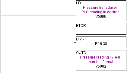
If you're a complete newbie at this and don't understand the ladder logic then don't worry about that. We'll get into ladder latter. Just understand that when you need to deal in fractions you'll most likely want to turn to real number formats in the PLC instruction set.
Sinking Deeper into Floating Point Numbers
Floating point is basically a representation of scientific notation. Oh yeah? What's scientific notation? Scientific notation represents numbers as a base number and an exponent. For example, 123.456 would be 1.23456 x 10². That 10 with a little 2 above is telling us to move the decimal two spaces to the right to get the real number. Another example, 0.0123 would be 1.23 x 10⁻². That little -2 indicates we move the decimal point in the opposite direction to the left. (Just a heads up, in the PLC you may be able to use scientific notation but in a different form like 1.23456E2 which is the same as a first example.) The number 10 here means we're dealing in decimal. We could just as easily do scientific notation in hexadecimal (123.ABC x 162) or even binary ( 1.0101 x 22, this binary one becomes important later on).
The Format
At some point in history a bunch of geeks got together and agreed upon a certain format or layout for a 32-bit floating point number. Due to a lack of originality, it officially became called "IEEE Standard 754". Here it is in all it's glory.
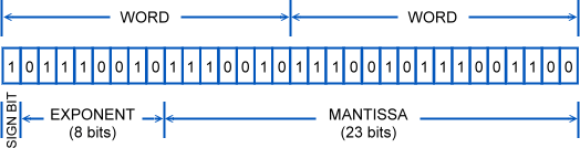
The exponent is the same as our little number above the 10 in scientific notation. It tells us which way the decimal should go so it needs to be positive (go to the right) or negative (go to the left). Here we are again trying to deal with negative numbers but in this case the geeks decided to use what's called a bias or offset of 127. Basically this means that at a value of 127 the exponent is 0. Any number below 127 will cause a negative exponent. Any number above 127 will be a positive exponent. So a stored value of 200 indicates an exponent of 73 (200-127).
The mantissa (or significand, if that is any easier to say) represent the precision bits of the number. In our example above it was the 1.23456 part of the scientific notation.
The final nomenclature in scientific notation would be: (sign) mantissa x baseexponent
Normally the base would be 10 but in this case it will be 2 since we are only dealing in binary. Since it's in base 2 (or binary) there's a little optimization trick that can be done to save one bit. Waste not, want not, you know. The trick comes about by realizing that scientific notation allows us to write numbers in many different way. Consider how the number five can be
5.00 x 100
0.05 x 10²
5000 x 10-3
These are all the same number. Floating point numbers are typically in a normalized form with one digit to the left of the decimal (i.e. 5.00 x 100 or 4.0 x 10³). The exponent is always adjusted to make this happen. In terms of using binary we'll always have a 1 in front (i.e. 1.0 x 23). You wouldn't have 0.1 x 24 as it wouldn't be normalized. So in this case it's always safe to assume that the leading digit is a 1 and therefore we don't have to store it. That makes the mantissa actually 24 bits long when all we have are 23 bits of storage. Ah, what we do to save one bit.
WARNING: It's Not a Perfect World
With all this power using floating point you are probably thinking, "I'll just use it all the time". There's a problem though as this method can actually lose some precision. In many cases it will be negligible and therefore well worth it to use real numbers. In other cases though it could cause significant errors. So beware.
Consider what would happen if the mantissa part of the floating point format was actually longer then 24 bits? Something has to give and what happens is the end is truncated, that is, it is cut off the end and lost.
Here's an example of a 32-bit number
11110000 11001100 10101010 00001111 which would be 4039944719 in decimal
In floating point with only 24 bits it would have to be
1.1110000 11001100 10101010 x 231 which when coverted back would be
11110000 11001100 10101010 00000000 and therefore 4039944704 in decimal.
That's a difference of 15. During normal math this might not be of concern but if you are accumulating and totalizing values then that kind of error could really make the bean counters mad. This is simply a case of knowing your limitations.
Glutton for Punishment: Further Reading
There's more on this subject concerning things like double precision, overflow, zero and 'not a number' which you can read about in these excellent articles.
What Every Computer Scientist Should Know About Floating-Point Arithmetic
IEEE Standard 754Floating Point Numbers
Introduction to Floating point calculations and IEEE 754 standard
ASCII ... and ye shall receive
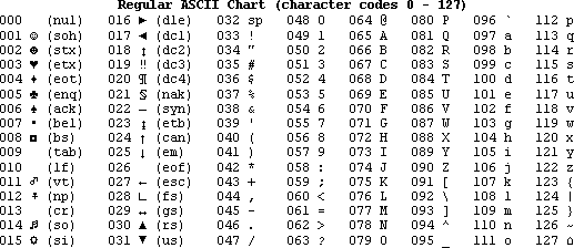
ASCII Chart ">ASCII is an acronym for American Standard Code for Information Interchange. You can see now why they shortened it down to ASCII which is pronounced as 'askey' by us geeks. This is the most common code for the exchange of letters and control characters between computers and their peripheral devices like printers. It is a standard that provides an easy way for the letters on our monitors to get into a binary format that a computer can understand. Thus it also finds its way into our everyday PLC lives in form of serial transmission to a display or printer.
All the assigned ASCII codes can be represented with 7 bits. Remember from our binary chapter that 7 bits of binary represent 128 in decimal. Typical PLCs though have 8 bits of data and therefore the left over bit is used for parity checking just to make sure everything is transmitting correctly. The following chart shows all the assigned letters, numbers and control characters with the computer number on the left and the symbol on the right. Some of these look weird because this stuff goes way back to the days when you had to control teletypes and phone lines. These days I'm typically only concerned with 10 (line feed), 13 (carriage return) and 32 through 126.
International Codes
In a lot of ways ASCII is very restrictive because the A stands for American and so it basically serves only English. Until recently the computer world has been trying to catch up to the many different languages in the world and the need for computers to be able to use them all. Thus there are many different character sets for other languages. The Alphabet Soup is a great resource to locate a language and it's corresponding character set. The real advance though has come with the advent of Unicode which is one standard representing all the languages of the world. Unicode has and will continue to supersede all these other types of alphanumeric codes because it simplifies the use of multiple languages. The list of possibilities is endless so if you ever need to program in Ugaritic then you got it.
The ABCs of BCD
Binary Coded Decimal (BCD) is a number code that makes all those 1s and 0s in the computer easier for humans to read. In BCD the digits 0 through 9 are stored as 4 bits (a.k.a. a nibble). Thus in a 16-bit word you can have four digits (16 bit word / 4 BCD bits = 4 digits). The figure below demonstrates how to convert a binary number to it's BCD equivalent.
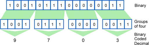
The astute student will see that this is a lot like converting from binary to hexadecimal. In this case though there are no letters like A through F which is part of making it easier to read.  In a pure binary sense the 16-bit word can have a value of 0 to 65535 but BCD limits us from 0 to 9999.
What is BCD good for?
Most modern control system components like PLCs and HMIs (for example AutomationDirect) make the use of BCD seamless. That is, you use them like you would decimal numbers without knowing the difference. There comes a time though when you'll need to know the difference (for instance when setting up an I/O card).
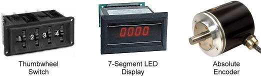
The real use of BCD comes in older types of controls like thumbwheel switches, 7-segment data displays and absolute encoders. For example, the thumbwheel switch will have (at least) four outputs for one digit which represent the binary numbers of that digit. Ganging the thumbwheel switches together then makes a word in BCD format.
The Black and White of Gray Code
Gray code (named after it's inventor Frank Gray) is a sequence of binary numbers where only one bit changes at a time. Marching through the integer sequence then only requires flipping one bit at a time which in certain applications drastically reduces any errors. In standard binary many digits can change at once, for instant when going from 7 to 8 (0111 to 1000) there are four bits changing state.
It's a fact of life that a PLC input can turn ON quicker then it can turn OFF. We're talking milliseconds here but with equally fast scan times it can generate a wrong reading when using normal binary methods. With Gray code you can be assured that only one bit is going to change. Anymore then that one bit changing and there is something wrong.
The problem is demonstrated in the figure below. For example, let's say it takes an input signal 300 milliseconds to come ON but it takes 500 milliseconds to go OFF. In binary then when going from 7 to 8 the ON bit will come on first but the bits that are ON are still ON and therefore the decimal value is 15. It takes another 200 milliseconds for the ON bits to go OFF and achieve our proper reading of eight. On the other hand, with Gray code notice that only one bit is changing from OFF to ON and therefore there is no error.
Here's how the sequence in Gray code starts and you can compare how different it is to standard binary code. I've made it easy by emphasizing the bits that are changing.
| Decimal | Binary People: Learning your 1s and 0s.">Binary | Gray Code |
| 0 | 0000 | 0000 |
| 1 | 0001 | 0001 |
| 2 | 0010 | 0011 |
| 3 | 0011 | 0010 |
| 4 | 0100 | 0110 |
| 5 | 0101 | 0111 |
| 6 | 0110 | 0101 |
| 7 | 0111 | 0100 |
| 8 | 1000 | 1100 |
| 9 | 1001 | 1101 |
| 10 | 1010 | 1111 |
| 11 | 1011 | 1110 |
| 12 | 1100 | 1010 |
| 13 | 1101 | 1011 |
| 14 | 1110 | 1001 |
| 15 | 1111 | 1000 |
Another neat trick is you'll notice that going from 15 to 0 still preserves our Gray code of only changing one bit. Pretty neat, eh? This is why they call it a cyclic code because it can go around in circles.
What is Gray Code good for?
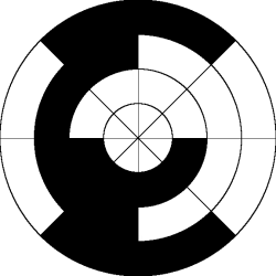
In automation it's particularly good for position transducers used to measure the angle of a shaft. This application benefits from the cyclic nature of Gray codes, because the first and last values of the sequence are different by only one bit. That is, if you feel like going round and round in circles.
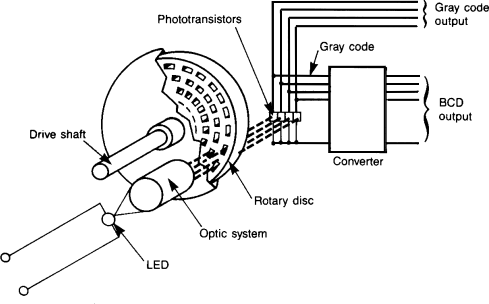
In an optical absolute encoder there is a disk with a Gray code pattern like so...
The Decision Makers: AND, OR and NOT
Life is full of decisions. What is true for us is also true of PLCs. We gather information (input) and based on that we make choices that determine our output. All though I've always found computers to be quite a bit more logical then human beings.
For an example of how we use logic in everyday life consider these statements:
- If Tommy OR Bob want to play basketball then I'll play too.
- It's 6 o'clock AND I'm NOT hungry therefore I'm going to keep playing.
- If Mom comes out AND orders me inside OR it get's dark then I'll stop playing.
Now these are pretty simple decisions especially if you're a ten year old boy. You'll notice that they all involve three types of comparisions: AND, OR and NOT. Now we could get more complex but all that we'd be doing is using these simple building blocks.
In the world of automation these types of TRUE or FALSE conditions come down to a device being ON or OFF, CLOSED or OPEN, PRESENT or ABSENT, 24 VOLTS or 0 VOLTS. In the PLC it all boils down to our now familiar binary system of a 1 or a 0. Typically having a bit ON represents a TRUE condition while OFF is FALSE. This is abitrary though as it may make more sense to use what is called failsafe logic and have an ON bit as a FALSE condition.
Let's turn again to some simple statements but this time using automation examples.
- When the button is pressed AND the door is closed then turn on the motor.
- If the process is done OR the emergency stop button signal is NOT on then turn off the motor. (This is an example of a failsafe operation as the emergency stop button could be pressed or the wire has been disconnected. In either case we want to check this for safety reasons. Relying on a signal to turn on when a wire has fallen off long ago may cause an awkward moment when we truly have to stop the machine in an emergency.)
- If the tank is full OR the button is pressed AND there are no alarms then start the process.
It would be nice to program like this but computers like to be a little bit more structured. A series of graphical objects have been used for years to represent these logic elements and they can be easily converted to a common ladder logic equivalent. These functions are also called gates as they act like gate keepers for different logic.
The NOT function
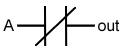
The simplest of all logic functions is the NOT gate.

It's sole function in life is to invert of flip the logic state. So an input of 1 will come out as a 0 and visa versa. Shown below is a truth table (it doesn't lie) showing all possible inputs and the resulting logical output.
| Input A |
Output |
| 0 | 1 |
| 1 | 0 |
The ladder logic equivalent for a NOT function looks like a normal contact but with a slash through it.
The AND function
The AND gate is associated with the following symbol that can have any number of inputs but only one output.
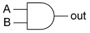
The truth table below shows that the output is only turned on when all the inputs are true (1). An easy way to remember this is AND works like multiplication.
| Input A |
Input B | Output |
| 0 | 0 | 0 |
| 1 | 0 | 0 |
| 0 | 1 | 0 |
| 1 | 1 | 1 |
The ladder logic equivalent for an AND function looks like two normal contacts side by side.
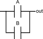
The OR function
Last but not least the OR gate is associated with the following symbol that also can have any number of inputs but only one output.
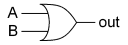
The truth table below shows that the output is turned on (1) when any of the inputs are true (1). An easy way to remember this is OR works like addition.
| Input A |
Input B | Output |
| 0 | 0 | 0 |
| 1 | 0 | 1 |
| 0 | 1 | 1 |
| 1 | 1 | 1 |
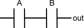
The ladder logic equivalent for an OR function looks like two normal contacts on top of each other.
Combining AND or OR with NOT
The NOT gate might not look like much help if you haven't programmed much but you'll find yourself actually using it frequently. It's very common to use it in combination with AND and OR. So the engineering gods decided to make some symbols for these combinations.
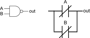
Putting the NOT and AND gates together forms the NAND gate. The truth table below shows that it is simply an inverted output of the AND gate.
| Input A |
Input B | Output |
| 0 | 0 | 1 |
| 1 | 0 | 1 |
| 0 | 1 | 1 |
| 1 | 1 | 0 |
A little circle (or if you like, a bubble) at the end of a AND gate is used to signify the NAND function. It's symbol and corresponding ladder logic are shown below. Now pay close attention to the ladder logic because the contacts are in parallel and not in series like the AND function.
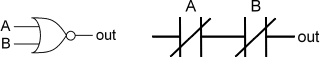
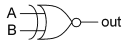
Putting the NOT and OR gates together forms... you got it... the NOR gate. The truth table below shows that it is simply an inverted output of the OR gate.
| Input A |
Input B | Output |
| 0 | 0 | 1 |
| 1 | 0 | 0 |
| 0 | 1 | 0 |
| 1 | 1 | 0 |
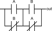
Again a little circle is placed at the end of an OR gate to signify the NOR function. It's symbol and corresponding ladder logic are shown below. The ladder logic is very different from the regular OR gate.
But wait! Don't order yet... the XOR gate.
So far with our logic gates we've covered almost all possible combinations except for one shown by the truth table below.
| Input A |
Input B | Output |
| 0 | 0 | 0 |
| 1 | 0 | 1 |
| 0 | 1 | 1 |
| 1 | 1 | 0 |
The logic to produce this output is called an Exclusive OR gate otherwise known as the XOR gate. It's a specialized form of the OR gate. So if either one of the inputs are on then the output is true, otherwise you're out of luck. The symbol for the XOR gate is shown by added a curved line to the OR gate symbol.

The ladder logic to implement an XOR gate is a little more complex then the others.
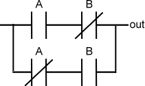
How useful is the XOR logic? You probably use the XOR gate everyday without thinking about it if you have a room with a light that works off two switches. If both switches are in the same position then the light will be off. Therefore just flipping one switch will turn the light on. In the PLC program this can be extremely useful for programming alternating actions or gray codes.
Ok, there is one more logic gate but I promise it is the last one. It makes sense that there is a XNOR gate which is the combination of the NOT and XOR logic. It simply inverts the output of the XOR function.
| Input A |
Input B | Output |
| 0 | 0 | 1 |
| 1 | 0 | 0 |
| 0 | 1 | 0 |
| 1 | 1 | 1 |
The symbol for the XNOR gate is shown below along with it's ladder logic equivalent.
Hope for the Future
While these terms and symbols may seem a bit esoteric for the PLC beginner they are important in the long run. A good grasp of these essentials will make PLC programming easier, simplier and save memory. The next lesson will make this clearer when we consider Boolean algebra.