PLC Programming HandbooksPopular ArticlesNavigationUser login |
Creating an Integrator Function Block in Modicon Conceptby C. Stanley This is the second article in a series that shows how to create user defined function blocks using Modicon Concept v2.6 programing software. This article will show how to create an integrator function block. Many basic control system component blocks contain an integrator function. Some examples are PID, Lead-Lag and filter blocks. An integrator function has an output that is the time integral of the input signal. out= K∫ in dt The integrator function described in this article will be an approximation of the above expression, where K represents the integrator gain and dt is the PLC scan time interval: out=K*∑in*scan interval.
Assign Inputs VariablesThe steps to create a new blank function block are not shown but can be found in the first article in this series on creating a summing junction. Click on Project then select Variable declarations on the drop down. Select inputs by clicking the Input radio button and enter the shown variables. The variables named out_min and out_max are limits on the value of the output. Variables init_ref and set_ref are used to preset or initialize the output of the integrator function. When set_ref is 1 or TRUE the output of the integrator is set to the value of init_ref. When set_ref is 0 or FALSE the integrator is operating. In all cases, the output of the integrator is constrained to be between the out_min and out_max limits.
Assigning Output VariablesClick on Output radio button and enter the shown variables. The variables at_min and at_max are set to 1 or TRUE, if the output out equals the value of the limits out_min or out_max. It is often useful to know when an integrator is maxed out. For example, the integrator output could represent a rotating vector’s angular displacement. Every time the displacement reaches 2π radians, external logic can reset the integrator to 0 radians. In this example the input would represent angular velocity of a vector rotating clockwise. The number of reset events would represent the number of turns of the vector. The integrator output would represent current position or displacement of the vector.
Naming the Integrator SectionClick the Project browser tool bar icon. Next, right click on Project: noname, and then click on New section.
Name the section integrator_sec as shown in fig. 4. Leave the default coding FBD radio button enabled.
Create a Programming Sheet for the Function BlockNext, right click (double left click does same) on the project drill down icon, as shown by the upper pointer on fig. 5 to bring up the newly created programing sheet.
Coding the Integrator FunctionUsing the tool bar icon Show FFB selection Dialog which is the icon pointed at by the upper right pointer in Fig. 6, place two arithmetic functions on the sheet. This is shown in Fig. 6. Using the tool bar icon Show Link creation mode which is the icon pointed at by the upper left pointer in fig. 6, wire the output of the MUL_REAL to the lower input of the ADD_REAL block. Finally assign the inputs to the function blocks as shown in Fig. 6. My previous article on creating a summing junction shows the wiring and variable assignment operations in more detail.
Click again on the Show FFB selection Dialog icon to bring up the FFBs from Library dialog box. This time click on the DFB button to select a user defined function block.
Fig. 8 shows a user defined function SCANTIME. This is a function I created to return the elapsed time in seconds of the last scan. The reader will not have such a function. I am using this function as a way to illustrate the introduction of time into the integration function I am creating. The integrator I am creating will work using this function. There is a problem. SCANTIME can only be called once per scan in a PLC program because it returns the elapsed time between calls. Calling it more than one time per scan may produce unpredictable scan times. I will resolve this issue later in this article. Knowing the scan time, which can be variable, is required in PLCs that control physical processes in real time. Each PLC manufacturer has different ways to determine scan times. The top end PLCs often have multiple mechanisms for scheduling sections of code based on time as well. One could place the integrator function in a fixed period scan schedule of say 10 milliseconds in a PLC that would provide this. In this case scan time would be a constant 10 milliseconds.
Working with the Selection BlockFig. 9 shows the selection of a Selection group in the IEC library and SEL function in that group. The SEL function is an un-typed or generic function that gets its type from the type of the variable assigned to its input. The output will be the same type as the input. The SEL block selects its output from one of two inputs based on the value of a BOOL input.
Wiring the SEL BlockThe SEL block G input is a BOOL type. When G is a 1 or TRUE the output is the value of IN1. When G is a 0 or FALSE the output is the value of IN0. The assigning variables to the SEL block is a sticky operation. In other words, once you assign a variable to a specific instance of SEL, that instance will always have that type as input and output. If you assign the input as a REAL one can not reedit that instance to accept an INT. One needs to delete the SEL instance and insert a new SEL block if the type of the inputs to the SEL block change. This reasoning applies to the rest of the generic or un-typed functions of Concept libraries. By the same reasoning, one needs to wire or assign inputs of the generically typed blocks before assigning the output. When editing function block sheets in Concept, one can select a function block that currently exists on the sheet by clicking it. The block will show it is selected by exhibiting a blue box around itself. Pressing Ctrl-C copies it to the clipboard. Paste it onto the sheet with a Ctrl-V. Copying generic typed instances in this manner also preserves the type of the copied instance, which may not be the type you need for your edit. It is best to get new instances of generic types such as SEL or MOVE.
Initialization CodingIn fig. 11, the SEL block G input was wired to an input set_ref. The IN0 was wired to the ADD_REAL output. The IN1 input is about to be wired to the init_ref variable. The integrator is initialized with the SEL block. The integration operation is actually done in the ADD_REAL block starting from the initial value on the next scan. Note that the out variable is used as an input and as an output. The SEL block is inserted in a position that allows it to over ride the output of the ADD_REAL. This allows the caller of the integration function to initialize the integrator whenever set_ref is a 1.
Implementing Integrator Upper LimitFig. 12 shows the selection of the Comparison group and GT_REAL function from the IEC library. The GT_REAL block will be wired to limit the integrator output to the value of the out_max input variable.
Implementing Integrator Lower LimitFrom the Comparison group select the LT_REAL function. The integrator limits are important in preventing windup. Windup occurs when the process error is such that an integrator accumulates a value that is way more than a physical device can accommodate. For example, a linear servo motor can only travel from 0% to 100% stroke. An integrator is used to hold the desired position of a servo motor which is only 0% to 100%. What will happen when this integrator accumulates a position of 10000% servo stroke? It will take a long time to unwind the integrator. What will the process be doing with the servo motor pegged at 100% while the integrator unwinds? Hopefully not damaging the rest of the plant! In using integrators, the programmer is interested in both the output value and the rate the integrator output changes for a given input. The input to integrators used in control systems is often a process error. The output of an integrator is often used to control a device that controls the physical process such as a valve-servo motor combination.
Fig. 14, shows comparison block wiring to limit integrator windup.
Using MOVE BlocksFig. 15 shows the selection of a MOVE block. MOVE blocks are curiously found in the Arithmetic group. The MOVE block can move just about any type of data to another location. MOVE blocks are generic instances that take the type of the first assigned input. As mentioned previously this assignment of a variable to a MOVE block input also assigns the type of the move. This assignment is sticky.
Hidden Enable PinsFig. 16 shows double clicking on the MOVE block bringing up an information window. By clicking the Show EN/ENO check box, the enable pin becomes visible. The enable pin makes the execution of a function block conditional. If the enable pin is 1, then the block will be executed. Conversely, if it is 0 the function will not execute. Concept works this way, however I have found considerable differences in PLC programing software. The MOVE block is particularly subject to varying functionality as found in other programming packages in regards to Enable pin function. For example, Rockwell RSLogix implements this functionality quite differently. There is often a difference in the functionality of the MOVE block between function block programs and ladder programs in the same programming package. Be sure to write test programs to determine exactly how a block such as the Move block works when switching between manufacturers programming packages or programming languages within the same package.
Multiple Assignment WarningsMultiple function blocks can assign outputs to the same variable. In fig. 17, this is shown. Without using Enable pins this could be an error and cause unpredictable results. Concept generates a warning about multiple assignments.
Coordinating Enable PinsThe two MOVE blocks in fig. 18 effectively clip the output of the integrator to be between the limits specified in the input parameters. A Move block is needed to pass the integrator output when it is not at one of the limits. To do this, I insert an OR block to control a yet to be inserted MOVE block. Coordinating enable pins can be tough because of execution order. In fig. 18 the function block execution order is listed in parentheses above the block. When editing sheets it is sometimes necessary to change execution order. I have found this trick: design the sheet to execute left to right ignoring the actual execution order. Select the whole sheet with a Ctrl-A, cut the whole sheet to the clip board with Ctrl-X, then paste clip board to sheet with Ctrl-V. The execution order will be reordered left to right and top to bottom. Pasting preserves the layout of the sheet but reorders execution.
In fig. 19 the wired OR block is shown, however the output of the OR block needs to be inverted for the .1.26 MOVE block function to pass the integrator output to out when the integrator is not limited out.
Invert Bool Pin ToolFig. 20 shows the use of the invert Bool tool. The upper pointer shows clicking on the invert icon on the tool bar. The cursor will change to the one shown just above MOVE block .1.26. Moving the cursor to the pin you would like to invert will show a check mark when the cursor is in the correct position to be applied. Inversion can be applied to BOOL input or output pins of functions. After inversion, the pin will show a small circle indicating its inversion.
How the Integrator WorksThe integrator works by multiplying the input times gain times time interval in seconds. The result is added to the output of the last scan. The SEL block provides for the resetting of the integrator to a new value init_ref when set_ref is 1. The final result is compared to the integration output limits: out_max and out_min.
More How the Integrator WorksThe inverted output of the OR_BOOL enables the upper most MOVE block to pass the integrator output to the out pin of the integrator block when the integrator is within limits. Otherwise, the other two MOVE blocks replace the output with their respective integrator limit.
Concept CONT_CTL Library IntegratorConcept CONT_CTL library has an integrator block that is similar to the one constructed in this article. Select the library as shown in fig. 23.
Concept Integrator BlockThe continuous control library has a block named INTEGRATOR. I pasted the block on to the work sheet for comparison purposes in fig. 25.
Concept INTEGRATOR BlockThe INTEGRATOR block has the same inputs as the one I constructed as shown in fig. 25. Double clicking on the INTEGRATOR block will bring up the information window. There is a help on type button on the information window. Clicking on this button brings up a substantial written description on this block. The next article in this series will be on derivative blocks and will include more about the help on type information. The INTEGRATOR block is interesting because it has a self contained notion of time that appears to my testing to be independent of scan time. The integrator developed in this article used my function block Scan_time as a time base. This use is not very satisfactory but served the purpose of describing integrator function. The Concept library function INTEGRATOR in my experience works very well. The integrator developed in this article would be more robust if the scan time were passed as an argument on an input pin.
Using the Comment ToolIn fig. 26, I use the Comment Tool. Clicking on it brings up a text dialog box in which you can enter comments. After clicking OK, the cursor will change to the comment placement cursor. Place the cursor where you would like the comment to appear and click again to drop it on the sheet. The comment cursor is sticky and allows additional comments to be dropped where needed. Pressing ESC key will return the cursor to normal. Comments can be moved by placing the cursor on it, hold down the left mouse key, and drag it to the new location. They can be cut/pasted to the clipboard as well. This completes the integrator article. As previously mentioned, the next article will be on derivative blocks. Both derivative and integrator blocks are used in the PID block. The PID block will be covered in a future article. ( categories: )
|
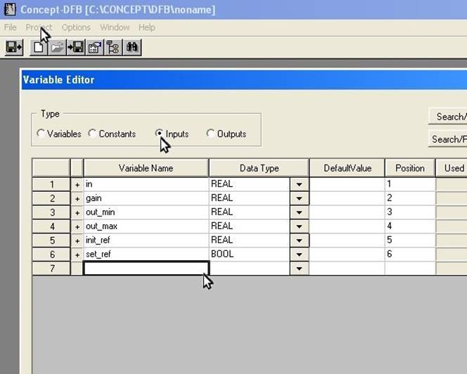 Fig. 1
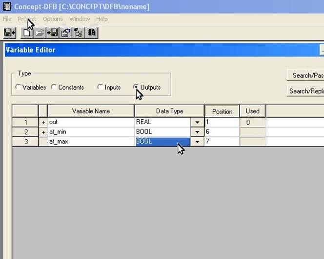 Fig. 2
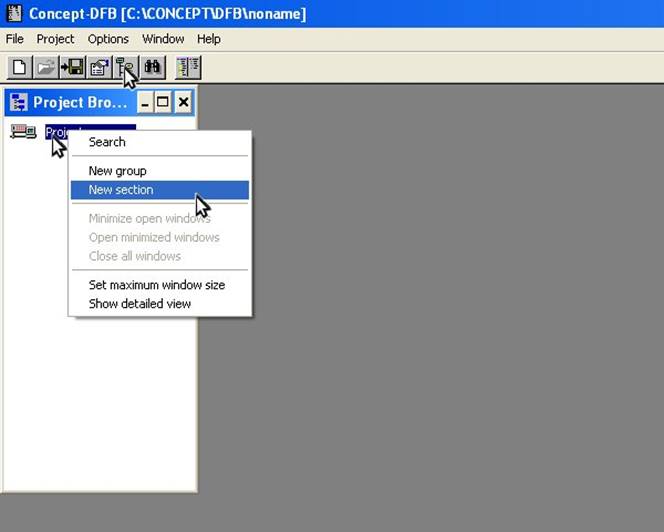 Fig. 3
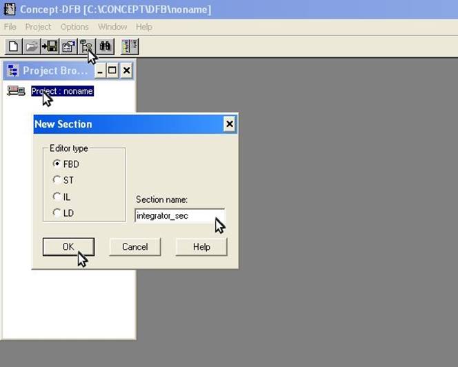 Fig. 4
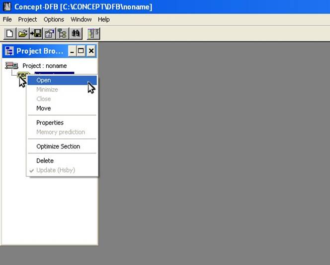 Fig. 5
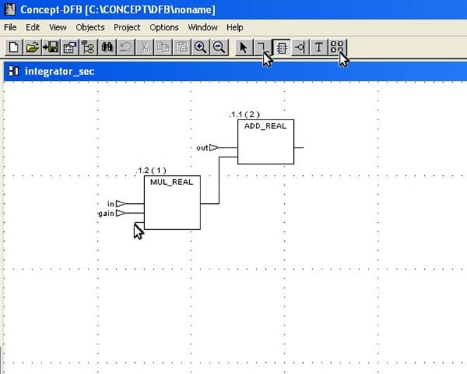 Fig. 6
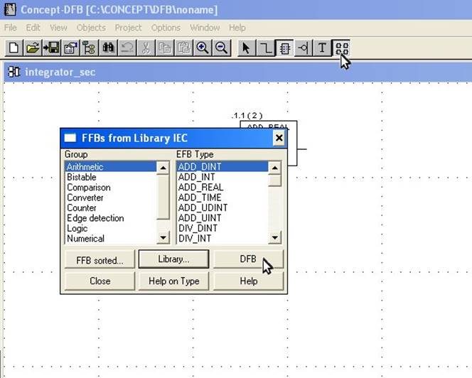 Fig. 7
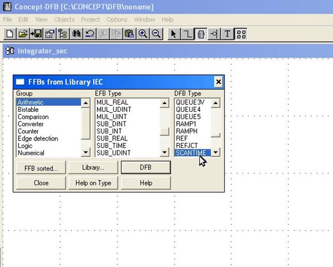 Fig. 8
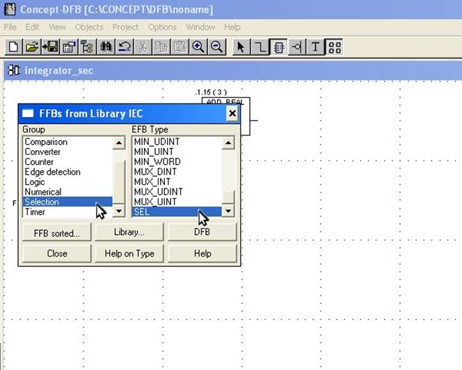 Fig. 9
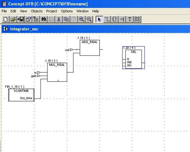 Fig. 10
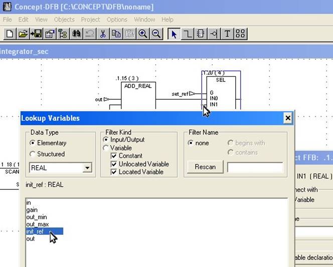 Fig. 11
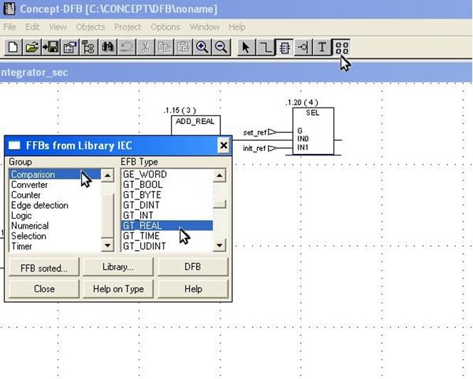 Fig. 12
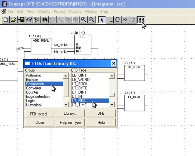 Fig. 13
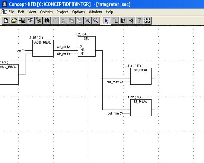 Fig. 14
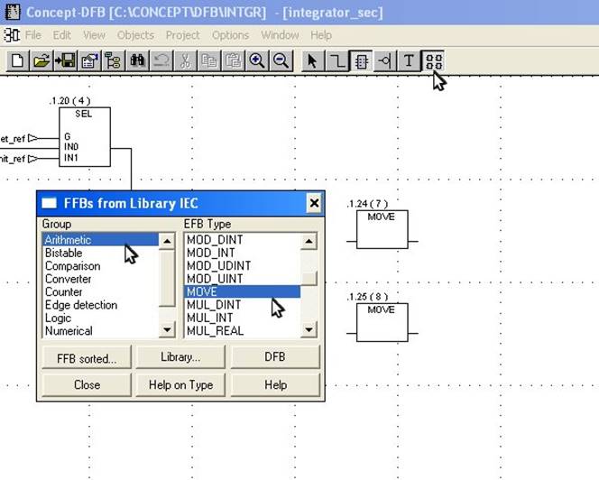 Fig. 15
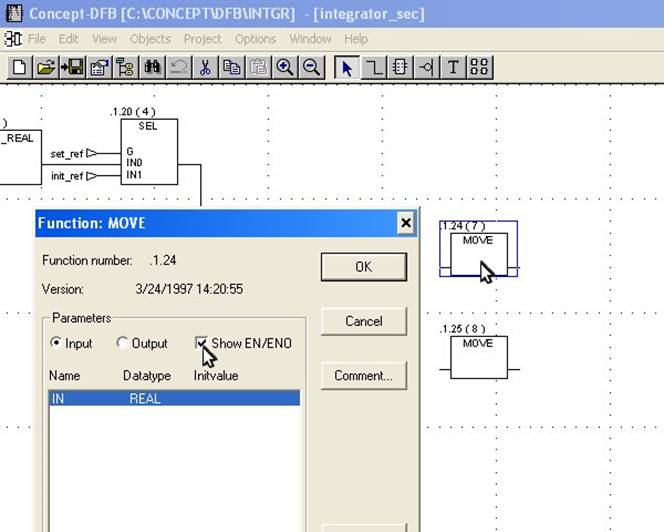 Fig. 16
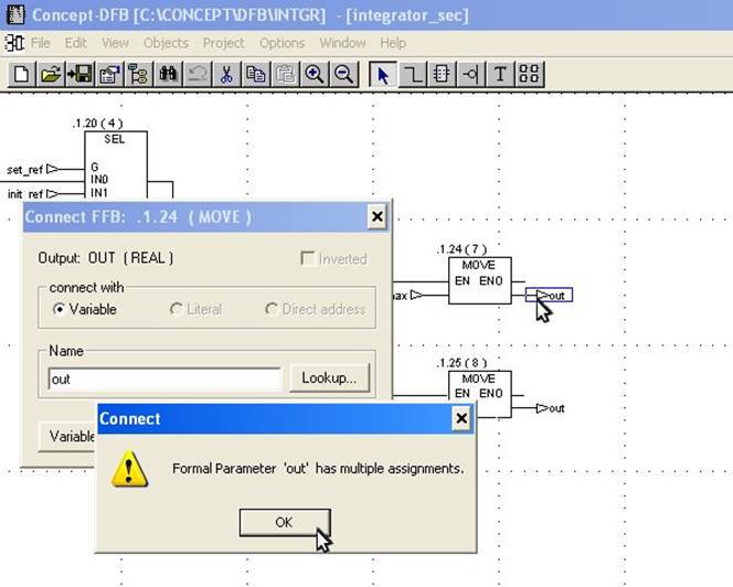 Fig. 17
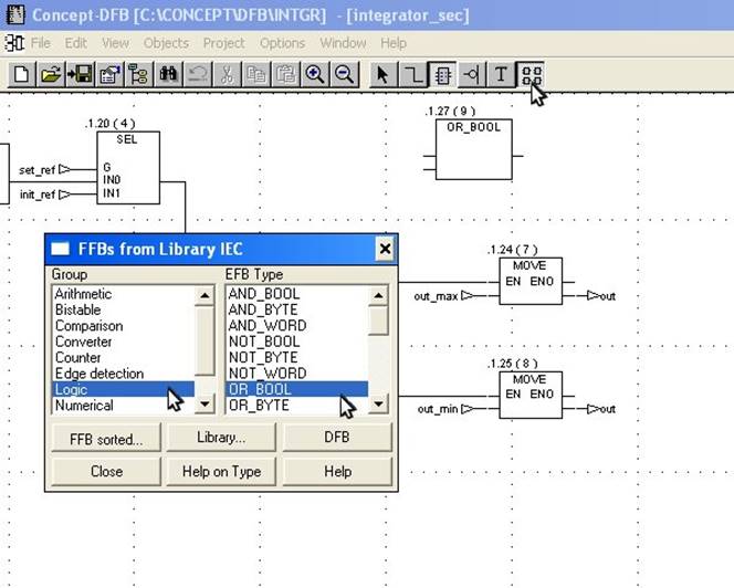 Fig. 18
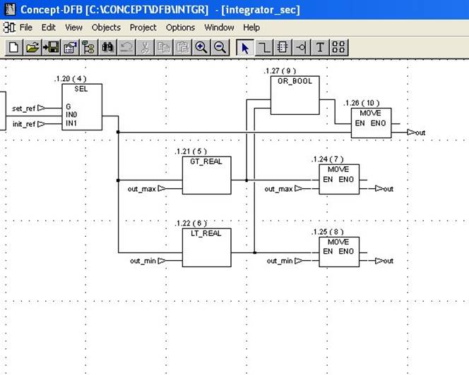 Fig. 19
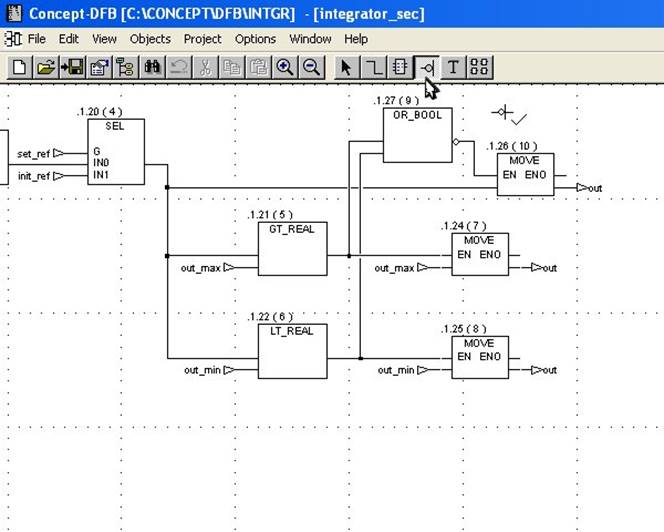 Fig. 20
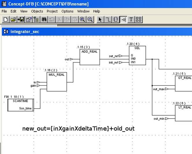 Fig. 21
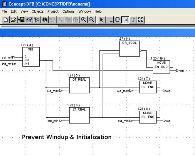 Fig. 22
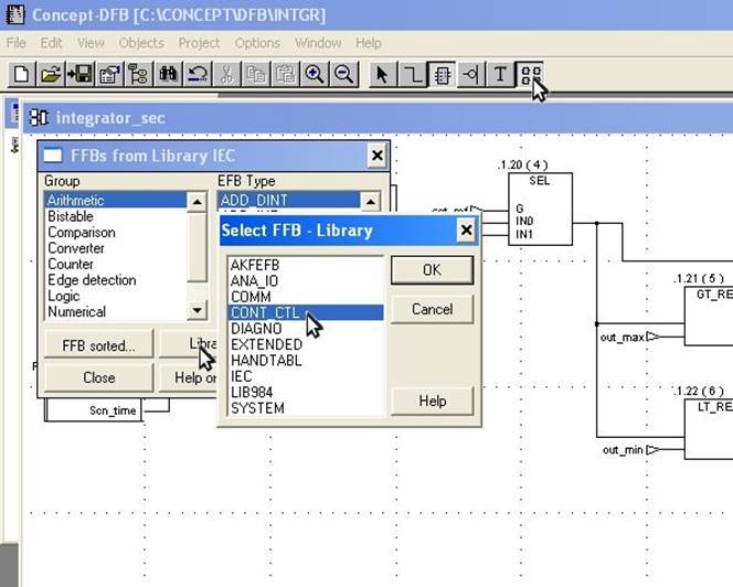 Fig. 23
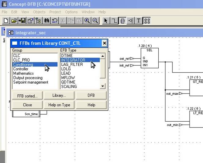 Fig. 24
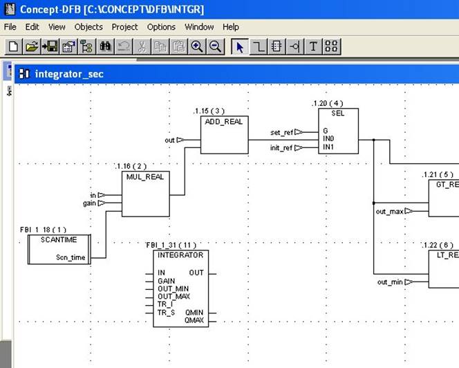 Fig. 25
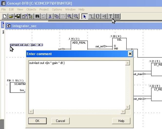 Fig. 26