PLC Programming HandbooksPopular ArticlesNavigationUser login |
How PLCs WorkA programmable logic controller is a specialized computer used to control machines and processes. It therefore shares common terms with typical PCs like central processing unit, memory, software and communications. Unlike a personal computer though the PLC is designed to survive in a rugged industrial atmosphere and to be very flexible in how it interfaces with inputs and outputs to the real world. The components that make a PLC work can be divided into three core areas.
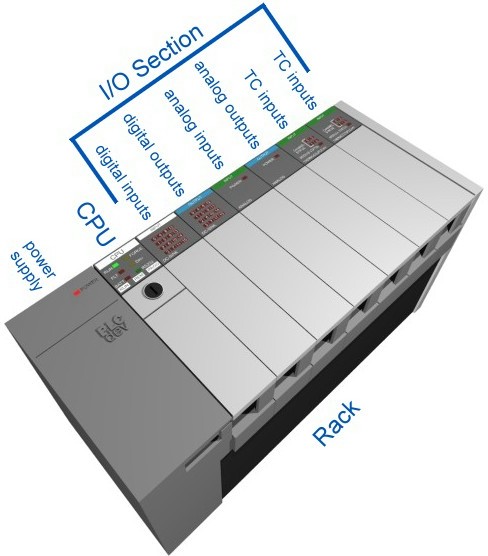
PLCs come in many shapes and sizes. They can be so small as to fit in your shirt pocket while more involved controls systems require large PLC racks. Smaller PLCs (a.k.a. “bricks”) are typically designed with fixed I/O points. For our consideration, we’ll look at the more modular rack based systems. It’s called “modular” because the rack can accept many different types of I/O modules that simply slide into the rack and plug in.
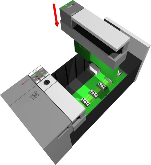
 The Power Supply and RackSo let’s start off by removing all our modules which leaves us with a naked PLC with only the power supply and the rack.
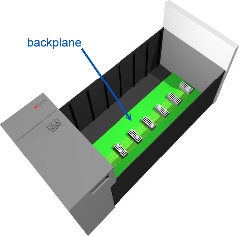
The rack is the component that holds everything together. Depending on the needs of the control system it can be ordered in different sizes to hold more modules. Like a human spine the rack has a backplane at the rear which allows the cards to communicate with the CPU. The power supply plugs into the rack as well and supplies a regulated DC power to other modules that plug into the rack. The most popular power supplies work with 120 VAC or 24 VDC sources. The CPUThe brain of the whole PLC is the CPU module. This module typically lives in the slot beside the power supply. Manufacturers offer different types of CPUs based on the complexity needed for the system. The CPU consists of a microprocessor, memory chip and other integrated circuits to control logic, monitoring and communications. The CPU has different operating modes. In programming mode it accepts the downloaded logic from a PC. The CPU is then placed in run mode so that it can execute the program and operate the process.
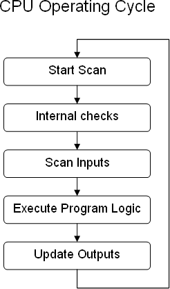
Since a PLC is a dedicated controller it will only process this one program over and over again. One cycle through the program is called a scan time and involves reading the inputs from the other modules, executing the logic based on these inputs and then updated the outputs accordingly. The scan time happens very quickly (in the range of 1/1000th of a second). The memory in the CPU stores the program while also holding the status of the I/O and providing a means to store values.
I/O SystemThe I/O system provides the physical connection between the equipment and the PLC. Opening the doors on an I/O card reveals a terminal strip where the devices connect.
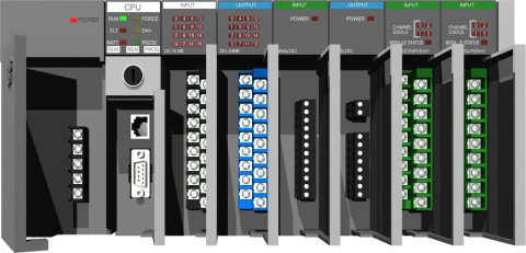
There are many different kinds of I/O cards which serve to condition the type of input or output so the CPU can use it for it’s logic. It's simply a matter of determining what inputs and outputs are needed, filling the rack with the appropriate cards and then addressing them correctly in the CPUs program.
Inputs Input devices can consist of digital or analog devices. A digital input card handles discrete devices which give a signal that is either on or off such as a pushbutton, limit switch, sensors or selector switches. An analog input card converts a voltage or current (e.g. a signal that can be anywhere from 0 to 20mA) into a digitally equivalent number that can be understood by the CPU. Examples of analog devices are pressure transducers, flow meters and thermocouples for temperature readings Outputs Output devices can also consist of digital or analog types. A digital output card either turns a device on or off such as lights, LEDs, small motors, and relays. An analog output card will convert a digital number sent by the CPU to it’s real world voltage or current. Typical outputs signals can range from 0-10 VDC or 4-20mA and are used to drive mass flow controllers, pressure regulators and position controls. Programming a PLCIn these modern times a PC with specially dedicated software from the PLC manufacturer is used to program a PLC. The most widely used form of programming is called ladder logic. Ladder logic uses symbols, instead of words, to emulate the real world relay logic control, which is a relic from the PLC's history. These symbols are interconnected by lines to indicate the flow of current through relay like contacts and coils. Over the years the number of symbols has increased to provide a high level of functionality. The completed program looks like a ladder but in actuality it represents an electrical circuit. The left and right rails indicate the positive and ground of a power supply. The rungs represent the wiring between the different components which in the case of a PLC are all in the virtual world of the CPU. So if you can understand how basic electrical circuits work then you can understand ladder logic. In this simplest of examples a digital input (like a button connected to the first position on the card) when it is pressed turns on an output which energizes an indicator light.
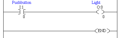
The completed program is downloaded from the PC to the PLC using a special cable that’s connected to the front of the CPU. The CPU is then put into run mode so that it can start scanning the logic and controlling the outputs. |
thanks
i dont know anything about plc before visiting this site..
but
this site gave me basic idea of how plc works. its explanation is so simple that anyone can understand it
.now i can go ahead with plcs thanks a lot
PLC
Very good information. easy to understand.What is the differece between isolated output and isolated output? Also the arrangement of cards in the slots - is it okay to use any slots for input or output ? Also explain the meaning of the symbols used in the ladder diagram - like I, O and zero, one etc?
Thanks
Very good site to understand
Very good site to understand wat is PLC? nice.
I also want to ask to include in more specific details
very nice site to see about
very nice site to see about the PLCs and thanks for informations and guidlines .
About site
Hi,
i felt your website is very good for i can get nice answers for my Doubt.
Thanks & Regards
S.Bharani Dharan
I never believed that
I never believed that understanding plc could be this easy!
Thank you
This site is wonderfull thank you for the information given it is usefull and clear, if you could explain solid state systems in more detail it would be helpfull.
thanks, it is like very
thanks, it is like very good. follow it too.
Undoubtly, this page is very
Undoubtly, this page is very useful because plc explanations are made very simple.
Does sound logic connecting a relay(50,51,87) through a plc for tripping breakers?
Thanks for the information
Thanks for the information given. It is simple to understand
the article is a good
the article is a good one.... bt can u plz gv me a brief idea wat kind of plc shld i use for handling 20 analog i/p's, 10 digital i/p's, 15 analog o/p's nd 5 digital o/p's?
great info
I use to think plc is rock scientist, but now i realise how easy and simple it is.
Seriously, Thanks
This website is a great help and it provides basic but very important information. It is exactly what I was looking for
Thanks..........
Thanks..........
Coments
Nice topic on Plc.
really it will helpful for
really it will helpful for my life go-ahead
FINALLY someone explained
FINALLY someone explained what do all the boxes do. Thank you very much.
How a PLC works
thank very much for your information, it really helped me for the literature review i wanted for my project
so great information ....,
so great information ...., Really thanks
good
good