PLC Programming HandbooksPopular ArticlesNavigationUser login |
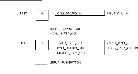
An Introduction to Grafcetsby John Schop I often find that using SFC's or Grafcets is the easiest way to design industrial automation systems. I have worked for several machine builders, and one of them had given the term 'SFC logic' another meaning. There was absolutely no process in their PLC logic that was not documented by an SFC or as I like to call it, a Grafcet. After some getting used to that, I absolutely loved the way it enabled me to program and troubleshoot complex machinery, and ever since, I've tried to use this method whenever I could. I seriously believe that no machine cannot be programmed with this method, and if I would have the opportunity to make the decision every time (unfortunately the customer is often involved in this), I would never use anything else. What is even better is that with a little bit of programming skills, it is possible to translate these Grafcets to ladder logic. This means nobody has to buy the expensive SFC programming modules, it is easy to read and troubleshoot, and less skilled maintenance people that you often have to deal with are not completely lost in a pile of spaghetti. This also means that your Grafcet documentation for a certain machine does not change with the manufacturer of the PLC you are using. The translated logic is the only thing that is slightly different. Of course, there are numerous ways of programming a Grafcet in ladder logic, but it is good to have a standard way of doing it every time, and I will show you how I do it. This article uses RSLogix 5000, but it is the same concepts in any PLC, with some minor differences. We are going to look at a little Grafcet first, so we get the idea of what is going on. Let us assume I have a simple cylinder (CYL1) that will have to move out, when a pushbutton is pressed. Once the pushbutton is released, the valve that operates the cylinder returns to its normal state, and the cylinder will move in (the rest position). Some other assumptions:
This probably requires some explanation, because over the years, I have developed this way of notation, which does not necessarily follow the strict rules of IEC1131 or whatever other standards there may be, but I'm assuming that if you read this, you understand the concept of steps and transitions. Look at the transition from Step 0 to Step 1, it says, 'INPUT_PUSHBUTTON * CYL1_INTERLOCK' which in my world means: 'the input from the pushbutton needs to be there, AND the interlock needs to be satisfied'. That would be a whole lot to write down in your documentation though, so that is why I do it that way. In case I need an 'OR', I use the '+' sign. The transition from Step1 to Step 0 says, '/INPUT_PUSHBUTTON', which means 'NOT that input'. On the right side of the steps, you see what is actually going to happen in that step. Step 0 does nothing except that we will tell the rest of our program that CYL1 is in, with 'CYL1_STATUS_IN', which is a Boolean variable that is true if we are in step 0, and the input from the prox 'INPUT_CYL1_IN' is true. Doing it this way makes sure we only use that input in one spot in our program, so if we ever have to change the physical location of that input, we only have to change our program in that one spot. In Step 1, we are going to do some more stuff. For example, if 'INPUT_CYL1_IN' is not true, we're starting a timer 'TIMER_CYL1_OUT', and after that timer has expired 'TIMER_CYL1_OUT.DN', we will make 'CYL1_STATUS_OUT' true. In addition, we have to energize the actual output 'OUTPUT_CYL1_OUT'. Now, to translate all this to ladder logic, we will follow a certain order of things:
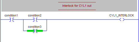
Let's see what it looks like in logic, step by step: 1. Gather information about interlocks:
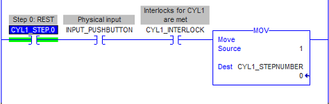
As you can see, I have fantasized some conditions for this interlock. 2. Let's do the transitions, first Step 0 to Step 1:
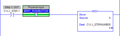
I've introduced some variables here, 'CYL1_STEP', which is a DINT that we're going to use the separate bits of to indicate a step, and also 'CYL1_STEPNUMBER', another DINT, to store our step number in. Step 1 to Step 0:
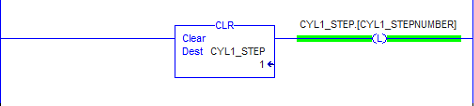
Now I use bit number 1 from our DINT called 'CYL1_STEP', to indicate that we're in Step 1, and I move a value of '0' into 'CYL1_STEPNUMBER', which will make us go back to Step 0 after the: 3. Conversion to coils. This conversion to coils makes sure that every step is true for at least one PLC cycle after the transition. I use the value in 'CYL1_STEPNUMBER' to coil a certain bit in 'CYL1_STEP':
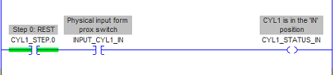
A little information on this one: because I latched the bit with an OTL instruction, I clear 'CYL1_STEP' first; to make sure we cannot have two steps at the same time. It is essential that not more than one-step can be active in one PLC cycle, and every step will be active for at least one PLC cycle at a time. You might have to read that last sentence a couple of times before its clear, but that is how it is. Now we are ready to do something within these steps: 4. Program the outputs, timers and status for a step: Let's do Step 0:
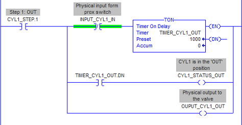
And then Step 1:
And that's all, really. Of course, in real life, you'll have to program some more stuff after this, like a diagnostic in Step 1, to indicate that the cylinder did not reach it's 'OUT' position within a certain time, and the same for Step 0 if it does not reach the 'IN' position. Another thing that might come in handy is a diagnostic to indicate that someone is pressing the pushbutton, but the interlocks are not ready yet, and I am sure you can come up with a lot more stuff like that. I am just trying to give you a basic idea of how to program an SFC real nice and clean in ladder logic, and more important, how to document them. A typical Grafcet that you would use in a program could of course be exactly like this, but most of the time you are going to need some more complex structures. If people are interested in that, I might elaborate on it later. I could probably write a whole book on it, now I am thinking about it. ( categories: )
|
Similar but simpler . . .
In Allen-Bradley, I do something similar, but I believe simpler and easier to follow. For me, each Step and the conditions (transition) to proceed to the next step are on one rung, all self contained. I don't have a way to show you my code here, but I will try to describe it.
'If Cyl1_StepNumber EQU 0,' (parallel branch down here), XIC input_cyl1_in, OTE cyl1_status_in, (parallel branch back up here)
Parallel branch: XIC input_pushbutton, XIC cyl1_interlock, MOV 1 to cyl1_stepnumber.
That's all there is to step zero. Restated in English:
If cyl1_stepNumber = 0
..... under these conditions do such and such
..... when these other conditions, MOV 1 to the cyl1_stepNumber (thus ending the execution of this step).
Step 1 looks the same, with both cyl1_stepNumbers incremented by one.
This way only one of these rungs can run at a time, and you are not trying to keep cyl1_stepNumber and cyl1_step.x in sync all the time. Just use the same value for both.
If you need to insure that each step never advance faster than once per scan, you can add an ONS OTE x, and then check to make sure x is off before advancing to the next step. This way, you won't ever advance during THIS scan.
The advantages I see are these: All step functions AND all the step's conditions to advance to the next step are contained in a single rung (with possibly several parallel branches). The code is so easy to read that I can show it to my customer and they can figure it out. Which means that I can figure it out too! And, like you said, when I get hit by a truck, someone else can figure it out too.
What do you think?
Well, that could be a way to
Well, that could be a way to do it. There's two reasons why I would not do it:
1. Sometimes a function is performed in more than one step, which in my version is easy, but in your version, you would have to do some more programming.
2. I do not like to use ONS instructions, and I would like to make sure my steps do not advance more than one cycle at a time.
But then again, the version I use might not be the Holy Grail of SFC programming.
Muy Intreresante....
Hola esta muy interesante, lo voy a compartir con mis colegas de twitte y mi blog... Saludos y gracias por la información...
Ing. Carlos Aquino
H. Matamoros. Tamps Mexico
Muy Intreresante....
Hola esta muy interesante, lo voy a compartir con mis colegas de twitte y mi blog... Saludos y gracias por la información...
Ing. Carlos Aquino
H. Matamoros. Tamps Mexico
This is great
Thanks for the great article! I teach PLC at Greenville Technical College is SC. We have just started to cover grafcets in class and last night one of my student found your article on a web search. I learned grafcets and programming as a tech at Michelin Tire Company in SC before becoming an instructor. It is a great programming method that allows technicians to use the program to find machine bugs very rapidly. I agree that any machine or process can benefit from the method. I haven’t seen a lot of support for it with North American companies but it does show up in most European companies. It would be great it more North American companies would adopt it. PS. This is now required reading for my class.
thanks
Thank you...I had not seen this response until now. Required reading even...I am honored.
How will you explain this to a plant electrician?
I understand how you are doing it here but it is hard to explain this to plant electricians. They will get confused. I have developed some standard step sequence logic (nothing fancy) which has been very easy to understand by all folks I had to explain over the years. When I find time, I will describe it on a forum. Basically it is a reusable code and if I am working with Siemens PLCs, it can be configured as an FB or several FBs making it more like object oriented programming. In A-B PLCs, I just use standard ladder to program it and use library import feature to bring in the base logic and then fill in the conditions and interlocks. In future, I plan on working a VB program so it will spit out the base code including conditions and interlocks which can then be used in PLC directly.. wishful thinking at the moment but doable!
I would also like to mention that most big companies I work with do not permit anything other than ladder logic in the programs so I stick to standard ladder logic.
The problem is not grafcet
The problem is not grafcet the problem is plant electrician, system are now more and more complex so people need to evaluate too. I like the grafcet philosophy it so simple when you need to start-up a system and for the maintenance it's so easy to debug, just check the step and what is missing in your transition and that's it.