PLC Programming HandbooksPopular ArticlesNavigationUser login |
Ladder Logic for a High Flow TotalizerSometimes there are limitations in dealing with very large values in a PLC. Floating point numbers (real numbers) often come to the rescue but in certain cases their precision can actually have adverse effects. These problems were mentioned in our article "Getting the Point about Floating Point Numbers". Take for instance a totalizer that deals with very large values. With one calculation the error is negligible but keeps adding them up and it starts to become significant. Being off by even 1 m3/hr after an hour is 60 m3/hr. Using integer values presents other challenges. The problem is that sampling a flow rate of 10,000 m3/hr every minute means a double register (max in BCD 99,999,999) will fill up (or overflow) in 9999 minutes or 6.9 days. If we switch to decimal we can do way better. A double register (max 4,294,967,295) will fill up in 429,496 minutes or 298 days. That may suffice for your needs but it's still less then a year. I need something better. Is there a better solution?To overcome these limitations a ladder logic example is laid out here that uses two totalizers in tandem. The problem is really in the sampling rate of every minute where the numbers can add up quickly. So the idea is to break down the minute sampling into an hour and use that value to add into our flow totalizer. This particular application was used to totalize a flow rate that varied up to 10,000 m3/hr. That's a lot of gas. It was designed on an Automation Direct DL250 PLC using their DirectSOFT software. If needed, I'm sure it could be refactored to any PLC type. The two totalizers are laid out in the Vmemory area along with associated registers to do some calculations. Keep in mind that two registers (a double word) is needed for all the instructions. Our final totalizer reading will be stored in V3000 (V3001). 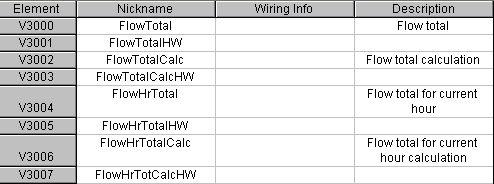
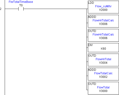
Rung 1 - Sample TimerFirst a pulse is programmed to fire every minute as a sampling time. 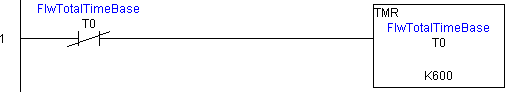 Rung 2 - Adding up Total FlowNow here's the trick. Taking our flow reading (V2000) we add it into a register set aside for calculating the total flow per hour (V3006). That value is dividing by 60 (minutes) to get a total flow per hour which we store in the FlowHrTotal register (V3004). The flow per hour is then added into our flow totalizer V3000.
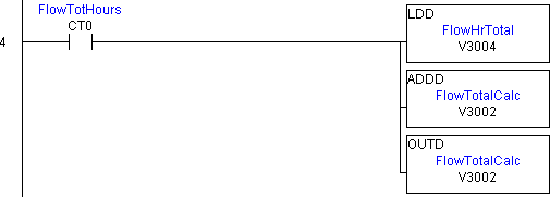
 Rung 3 - Hour CounterTo keep track when an hour goes by a counter (CT0) is set up to count up to 60 minutes. 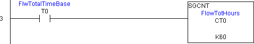 Rung 4 - Transfer of Hour TotalizerEvery hour the Flow Hour Totalizer (V3004) is added into the Flow Total Calculator register (V3002)
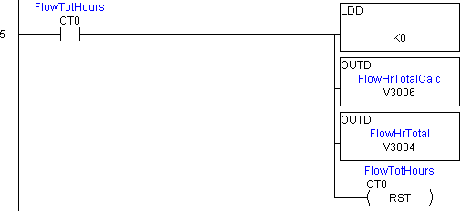
 Rung 5 - Resetting the Hour TotalizerOnce the hour flow totalizer is added in to the final totalizer we reset the hour totalizer by loading a zero into it's registers and reset the hour counter.
 Rung 6 - Resetting the Main Flow TotalizerOptionally, if the ability to zero the totalizer was needed we'd have to clear all these registers and reset the counter/timer. 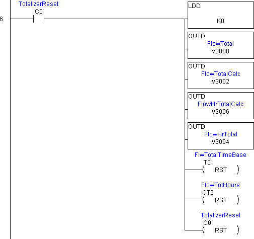 That's it. Plug it in and start totalizing.
|
Totalizer
I just plugged this into a DL06 plc and it won't work for me. The value of V3000 stays the same as all the other values
??
Excuse me, where is the TotalizerReset C0 source from? I saw the C0 contact and C0 reset coil only in the program. Please help..
Hi there, C0 is just an
Hi there,
C0 is just an internal relay. Automation Direct calls them control relays so that's why it is a C. In my application I have that coming on from a touch screen. The reset makes it go off once everything is reset. You may just want to use an input and forget about the reset on C0.
If water flow is in Litres/minute
Note if have 4mA at 0Litre/minute
20mA at 20Litre/minute
I have converted the analog values to engg values(0.0 to 20.0 litres)
If water flow is in Litres/minute then what will be values of Timer T0, Counter CT0