PLC Programming HandbooksPopular ArticlesNavigationUser login |
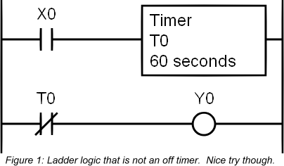
The Making of an Off TimerA staple of any PLC instruction set is the timer. The most common type is the "On Timer" while its brother the "Off Timer" suffers from misunderstanding and neglect. There are quite a few PLC manufacturers (you know who you are) who simply do not offer an off timer instruction. This is a shame because they are so handy for keeping something else on (i.e. a fan or light) for a given period after something has turned off. So if you’re one of those programmers who miss your off timers then stay tuned because we outline here how to create an off timer using an on timer. A Typical First ApproachAt first the problem may seem trivial. First attempts usually start by just inverting the output of the on delay timer.
This logic produces the following timing diagram.
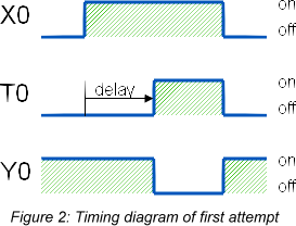
Unfortunately this is not an off delay timer. Of course, you didn’t expect it to be that easy. A true off delay timer has the characteristics below.
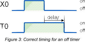
The off timer starts timing once the logic goes from true to false. It stays on for the given delay time and then turns off. So this deserves a little bit more brain power. Ladder Logic for an Off Delay TimerSuccess can be achieved by using some latching functions (SET and RST). The output will mimic the function of an off timer. When the input (X0) comes on the output (Y0) is latched on. The second rung does not start timing yet because of the input being a normally closed contact. Once the input is turned off the timer will begin timing but the output will stay on because it was latched. The third rung resets the output to false once the timer is done.
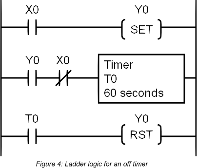
The ladder logic produces the following timing diagram with the output (Y0) acting just like an off delay timer.

Another Way to Create an Off TimerThere’s more then one way to skin a cat. The ladder logic shown below performs the same logic using a more conventional latching technique and thus it looks a little cleaner. The first rung is the same as the second rung in the first example---it will start timing once the input (X0) turns off. In the second rung, the output (Y0) is turned on immediately when the input comes on and it is latched on until the timer turns it off.

Whichever one you use is simply a matter of personal preference since the outcome is the same. Happy times are here again! ( categories: )
|
Good....
Good....