PLC Programming HandbooksPopular ArticlesNavigationUser login |
Siemens S7 Status WordIn Siemens PLCs the Status Word is an internal CPU register used to keep track of the state of the instructions as they are being processed. In order to use STL more effectively it is important to understand the Status Word and its functions. Each bit in the Status Word has a specific function to keep track of bit logic (RLO, STA), math (OV, OS), comparison operations (CC0, CC1) and whether the logic should continue, be nested or start new (/FC, OR, BR). Only the first 9 of the 16 bits are used. Bit Positions
Each instruction may do the following to each bit in the status word.
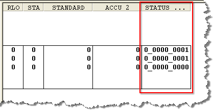
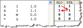
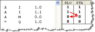
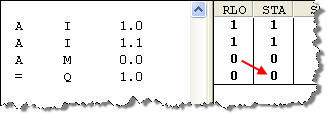
The status word can be seen by displaying the STATUS column while monitoring in STL view. The RLO (bit 1) and the STA (bit 2) are also displayed in the RLO and STA column.
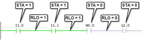
The Most Important Status Word Bits /FC – First Check (bit 0) If the /FC bit is a 0 then the instruction is considered to be the first instruction being processed. If the /FC is a 1 then the instruction being scanned will use the logic from the previous instruction. Certain instructions like =, S and R will set the /FC bit to 0 thus starting new logic after it. Other instructions like A or O will set the /FC bit to 1 signalling to combine the logic with the next instruction. RLO – Result of Logic Operation (bit 1) The RLO bit stores the running logic state of the currently processing instructions. Certain bit logic and comparison instruction will turn the RLO to a 1 when the condition is TRUE and write a 0 when the condition is FALSE. Other instructions read the RLO (=, S, R) to determine how they are to execute. STA – Status (bit 2) The STA bit reflects the state of the current Boolean address. Help with RLO, STA and /FC If you are used to ladder logic and struggling to understand the purpose of the RLO and STA it may help to visualize a rung like below. The STA is used to keep track of the state of the addresses. The RLO is used to keep track of the state of the rung.
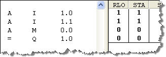
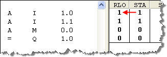
The equivalent STL is shown below.
It steps through the logic as follows:
The Other Status Bits OR (bit 3) The OR bit is used for combining AND functions before OR functions. OS – Overflow Stored (bit 4) In the event of an overflow (OV bit 5) the OS bit will store the value even after the OV bit has been reset. The following commands reset the OS bit: JOS (Jump if OS=1), block call instructions, block end instructions. OV – Overflow (bit 5) The OV bit is set by a math instruction with floating point numbers after a fault has occurred (overflow, illegal operation, comparison unordered). The OV bit is reset when the fault is eliminated. CC0, CC1 – Condition Code (bits 6 and 7) The Condition Code bits provide results for comparison and math instructions. Comparison Instructions
Math Instructions, without Overflow
Integer Math Instructions, with Overflow
Floating Point Math Instructions, with Overflow
Shift and Rotate Instructions
Word Logic Instructions
BR – Binary Result (bit 8) The Binary Result transfers the result of the operations ( categories: )
|
PCS 7
HELLO,
I have a question about the PCS 7!
I am learning a manual from SIEMENS which they describe some functions blocks in PCS 7 With the CFC editor !
my question are :
1 what is the difference between PCS7 and STEP7?
2. if the blocks functions are changed if I would use STEP 7 with the CFC library ?
3. any person does you use the CM 104 gateway from SIEMENS ?
THANK YOU
IEC61850
PCS7 and STEP7
The difference is very simple PCS7 has more functionality and in built libraries than STEP7, thus PCS7 is an advance version of STEP7. PCS7 is more like a software in which S7 400 can be configured as a DCS (PCS). Whereas through STEP7 you can only do PLC programing. On STEP7, you have to deal with analog DSP, whereas in PCS7 these details or handling is eased through the inbuilt library functions.
STEP 7 versus PCS7
Put simply, STEP 7 is a programming platform for the S7 Hardware platform. PCS7 (Process Controller S7) is a Simatic distributed controller platform, which is built upon the S7 hardware platform, and that uses the STEP 7 software.
The main difference, however, is that PCS7 includes software language extensions (e.g., CFC and HiGraph) to the standard STEP 7 languages (LAD, FBD, STL), as well as standard functions extensions (i.e. special libraries). There are also hardware extensions as well. These extensions are all aimed at providing a platform for distributed process control functionality.