PLC Programming HandbooksPopular ArticlesNavigationUser login |
Stage Programming Tutorial by Exampleby Garry Musgrave IntroductionPLC's (Programmable Logic Controllers) are a very useful control solution for a variety of exhibit and interactive applications. These general-purpose control devices can accept a number of inputs from such devices as pushbuttons, motion detectors, joysticks, etc. They can have multiple relay, analog, and serial outputs to control lights, motors, sound effects, etc. In between the inputs and outputs is a control program that determines which outputs are activated when certain combinations of inputs are received. Available programming resources include variables, timers, and counters. The principal drawback to these devices has been the steep learning curve and inherent difficulty with program maintenance using their traditional RLL (Relay Ladder Logic) programming language. By using state machine programming techniques, however, PLC programs can become very simple to create, and are easy to maintain and modify. A state machine model is a programming paradigm wherein the "machine" (i.e.: the controller) can only ever be in one of a set of distinct states (conditions) at any given time. While this concept may at first sound complex, it can actually lead to greater simplification - as we shall see. State machine programming can be done on any PLC through clever use of SET and RESET instructions and using internal contacts to direct flow. It is much simpler, however, if the PLC supports this type of programming directly. The good news is that now many do. The bad news is that they seldom refer to it as "state machine programming," nor do different manufacturers use the same term. You will see it referred to as "stage programming", "STL programming", "SFC programming" and various other terms. All of these have one thing in common: a special internal "contact" attached directly to the power rail controls flow into each state. This contact almost always has an 'S' designation (for state). The key concept is that one (and only one) state can be active at any one time, and all the logic in the other (inactive) states is disconnected from the power rail. Four Easy Steps
Step by Step ExampleRather than describing state machine programming in abstract terms, let's develop a simple real-world exhibit control application using state machine techniques. Much more complex programs can be built using exactly the same principals - interestingly, while a more complex program will certainly have many more states, each state will likely still be as simple as those in this example! Note that our example program transitions sequentially from one state to the next. This is not a requirement of state programming - you may jump from any state to any other. A more complex program will likely jump around based on varying input conditions. 1. Describe the function of the program. The first step in developing a state machine program (and, indeed, any program) is to clearly state the functional objectives: As a visitor walks through the display, a motion detector triggers the PLC. The PLC will then trigger a digital message repeater (DMR) to play one of several available sound effects. To prevent repetition, the sounds are selected at "random." A short delay is provided after each effect to prevent triggering of the next sound effect by the same visitor. Due to the inherent problems with random number generation, we will accomplish the "random" selection of the next SFX by using a look-up table that contains three sets of all available message numbers in a non-sequential order. 2. Identify and name your inputs and outputs. The next step is to analyse the functional description, and create I/O tables. We generally select a digital message repeater that has a contact that is active as long as the clip is playing - thus, the program doesn't care how long any of the individual SFX are. In our example, then, we have two inputs:
The message repeater we would select for this application allows us to select any of 32 clips at random by setting five of its input lines to a binary value and then strobing another input. Upon receiving the strobe, the DMR decodes the binary value and plays the corresponding clip. Thus, we have six output relays - all connected to the DMR:
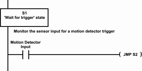
3. List the machine states. 4. Write the program. The next step is to analyse the functional description, and list each of the machine states. For clarity, we will show the result of step 4 immediately after each part of step 3: S0 - Initialization StateThis state should occur in virtually every program you create - it is the initial state that is always entered upon power up. It is executed once, and is never re-entered unless the PLC is powered down or a RESET occurs. This state is used primarily to initialise data variables. It is good programming practice to place all timer and counter data here, then load the timers and counters from the variables. This way, all of the data that you may want to modify during "fine-tuning" of the program is in one location - saving you searching through the program for the specific counter or timer and its "hard-wired" values. It also reduces mistakes due to altering the wrong timer value or inadvertently changing the program. In our example, this state will also initialise the message look-up table, and set up the look-up table pointer to point to the first message number in the table. When completed, it transitions to S1. For clarity, we will not show the ladder diagram for this state. S1 - Wait for Trigger StateMonitor the Motion_detector_input for a trigger from the motion detector. Upon receiving a trigger, transition to S2.
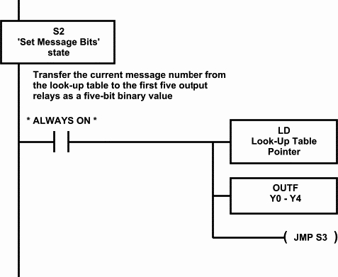
S2 - Set Message Bits StateTransfer the current message number from the look-up table to the Bitx output relays as a five-bit binary value, then transition to S3.
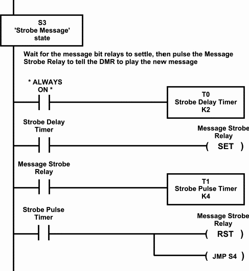
S3 - Strobe Message StateWait for a 0.2S delay to allow the bit outputs to stabilise, then pulse the Message_strobe_relay for 0.4S to signal the message repeater to play the message determined by the Bitx relays (i.e.: Y0 through Y4), then transition to S4.
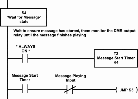
S4 - Wait for Message StateWait 0.4S to be sure the message has started playing, then monitor the Message_playing_input until the message has completed playback, then transition to S5.
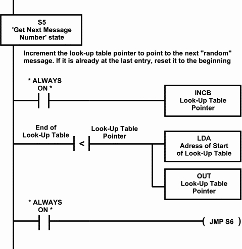
S5 - Get Next Message Number StateIncrement the look-up table pointer to make the next message in the "random" sequence the current message number. If it was at the end of the table, reset the pointer to the start. Then transition to S6.
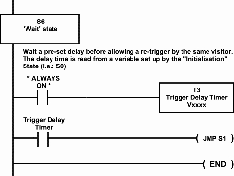
S6 - Wait StateWait a programmable duration to prevent an immediate trigger of the next sound effect by the same visitor. The delay value is determined by the value of a variable initialised in S0. Then transition to S1, and start the process again. NOTE: We never jump back to S0. The initial state is only executed once - whenever the PLC is powered up.
|


SET, RESET and JMP are bad news!
The problem I have with this article is that it advocates two of my biggest hates in Ladder programming.
1) The use of SET and RESET functions
2) The use of jumps and non sequential code
Don't get me wrong, these functions do have their usage, but their value is usually undermined by overuse and misuse, and one of the biggest misuses of them tends to be in state machines.
Once you force yourself to stop using these functions then you are on the path to becoming a much better Ladder programmer.
Um JMP is probably a part of
Um JMP is probably a part of the instruction set of probably over 90% of all processors sold. In fact your ladder logic probably when compiled contains JMP instructions.
Have to disagree on the "key
Have to disagree on the "key concept" wording. Parallel processes are possible and pretty useful in some applications, so "one and only one stage at a time" is an incorrect condition for having a working program. In AD (the PLC provider used in the examples) this is achieved by jumping to two stages and then adding a converging stage at the end of parallel process.
Great article otherwise. Stage programming rocks!