PLC Programming HandbooksPopular ArticlesNavigationUser login |
The Decision Makers: AND, OR and NOTLife is full of decisions. What is true for us is also true of PLCs. We gather information (input) and based on that we make choices that determine our output. All though I've always found computers to be quite a bit more logical then human beings. For an example of how we use logic in everyday life consider these statements:
Now these are pretty simple decisions especially if you're a ten year old boy. You'll notice that they all involve three types of comparisions: AND, OR and NOT. Now we could get more complex but all that we'd be doing is using these simple building blocks. In the world of automation these types of TRUE or FALSE conditions come down to a device being ON or OFF, CLOSED or OPEN, PRESENT or ABSENT, 24 VOLTS or 0 VOLTS. In the PLC it all boils down to our now familiar binary system of a 1 or a 0. Typically having a bit ON represents a TRUE condition while OFF is FALSE. This is abitrary though as it may make more sense to use what is called failsafe logic and have an ON bit as a FALSE condition. Let's turn again to some simple statements but this time using automation examples.
It would be nice to program like this but computers like to be a little bit more structured. A series of graphical objects have been used for years to represent these logic elements and they can be easily converted to a common ladder logic equivalent. These functions are also called gates as they act like gate keepers for different logic. The NOT functionThe simplest of all logic functions is the NOT gate.
It's sole function in life is to invert of flip the logic state. So an input of 1 will come out as a 0 and visa versa. Shown below is a truth table (it doesn't lie) showing all possible inputs and the resulting logical output.
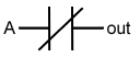
The ladder logic equivalent for a NOT function looks like a normal contact but with a slash through it.
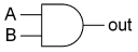
The AND functionThe AND gate is associated with the following symbol that can have any number of inputs but only one output.
The truth table below shows that the output is only turned on when all the inputs are true (1). An easy way to remember this is AND works like multiplication.
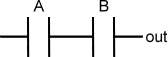
The ladder logic equivalent for an AND function looks like two normal contacts side by side.
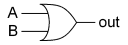
The OR functionLast but not least the OR gate is associated with the following symbol that also can have any number of inputs but only one output.
The truth table below shows that the output is turned on (1) when any of the inputs are true (1). An easy way to remember this is OR works like addition.
The ladder logic equivalent for an OR function looks like two normal contacts on top of each other.
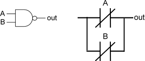
Combining AND or OR with NOTThe NOT gate might not look like much help if you haven't programmed much but you'll find yourself actually using it frequently. It's very common to use it in combination with AND and OR. So the engineering gods decided to make some symbols for these combinations. Putting the NOT and AND gates together forms the NAND gate. The truth table below shows that it is simply an inverted output of the AND gate.
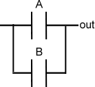
A little circle (or if you like, a bubble) at the end of a AND gate is used to signify the NAND function. It's symbol and corresponding ladder logic are shown below. Now pay close attention to the ladder logic because the contacts are in parallel and not in series like the AND function.
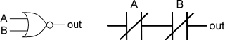
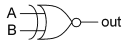
Putting the NOT and OR gates together forms... you got it... the NOR gate. The truth table below shows that it is simply an inverted output of the OR gate.
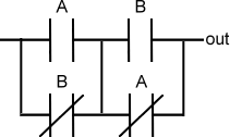
Again a little circle is placed at the end of an OR gate to signify the NOR function. It's symbol and corresponding ladder logic are shown below. The ladder logic is very different from the regular OR gate.
But wait! Don't order yet... the XOR gate.
So far with our logic gates we've covered almost all possible combinations except for one shown by the truth table below.
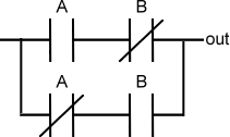
The logic to produce this output is called an Exclusive OR gate otherwise known as the XOR gate. It's a specialized form of the OR gate. So if either one of the inputs are on then the output is true, otherwise you're out of luck. The symbol for the XOR gate is shown by added a curved line to the OR gate symbol.
The ladder logic to implement an XOR gate is a little more complex then the others.
How useful is the XOR logic? You probably use the XOR gate everyday without thinking about it if you have a room with a light that works off two switches. If both switches are in the same position then the light will be off. Therefore just flipping one switch will turn the light on. In the PLC program this can be extremely useful for programming alternating actions or gray codes. Ok, there is one more logic gate but I promise it is the last one. It makes sense that there is a XNOR gate which is the combination of the NOT and XOR logic. It simply inverts the output of the XOR function.
The symbol for the XNOR gate is shown below along with it's ladder logic equivalent.
Hope for the FutureWhile these terms and symbols may seem a bit esoteric for the PLC beginner they are important in the long run. A good grasp of these essentials will make PLC programming easier, simplier and save memory. The next lesson will make this clearer when we consider Boolean algebra. |


This website is very
This website is very amazing! I love your interesting choice of words! I am a teacher and this really helps me make things interesting for my class!
I'm from Brazil, do not
I'm from Brazil, do not speak english very well and so poorly written, but I mean I loved that site, did not know him, but thanks, this is the guy. a big hug to everyone
its very nice
its very nice
thanks a lot.
thanks a lot.
the best website for plc
the best website for plc learners.
really no one like this
its the best site for the plc Lerner I will just say really there is no one like this'
Thank's a lot