PLC Programming HandbooksPopular ArticlesNavigationUser login |
A Quick Tutorial on RSLogix Emulator 5000RSLogix Emulator 5000 is a software simulator for the Allen Bradley line of Logix 5000 controllers (ControlLogix®, CompactLogix®, FlexLogix®, SoftLogix5800® and DriveLogix®). The goal is to mimic the function of a PLC without the actual hardware and thus do advanced debugging. More information can be found in the AB publication LGEM5K-GR015A-EN-P. As a quick introduction we’ll go through a simple example of setting up a simulation. This involves three major steps.
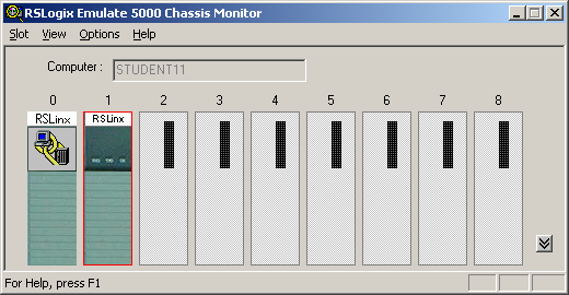
Setting up the Chassis MonitorTo start the Chassis Monitor, click Start > Programs > Rockwell Software > RSLogixEmulate 5000 > RSLogix Emulate 5000 Chassis Monitor. 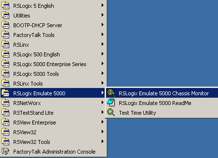 When the emulator opens up you’re confronted with what looks like an empty chassis. In slot 0 is an RSLinx module which has to be there for the emulator communications to work. Your slot 1 might have another irremovable RSLinx module depending if you are running RSLogix Enterprise.
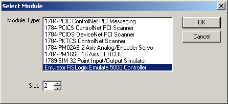
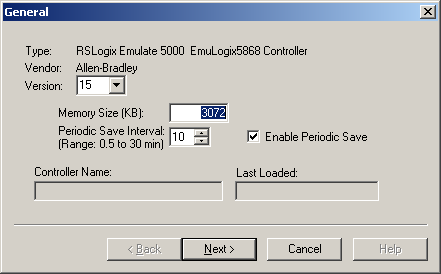
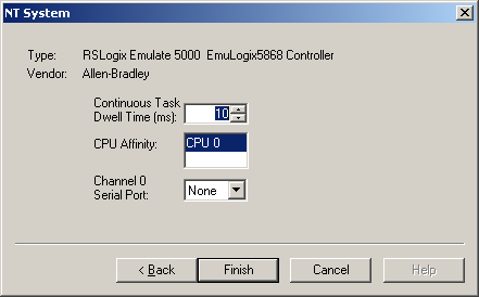
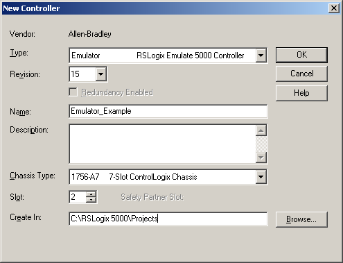
 From here we set up our hardware configuration for simulation. Our first step will be to add the CPU. In this case it is a special one called an Emulation Controller.
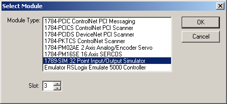
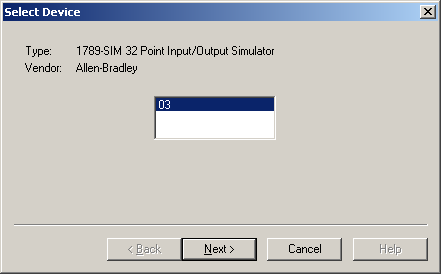
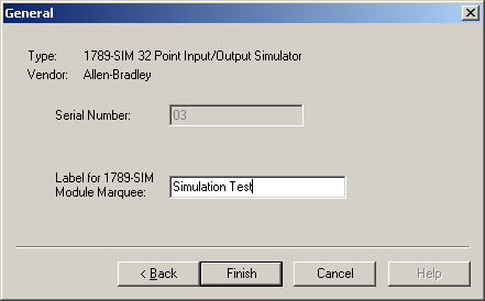
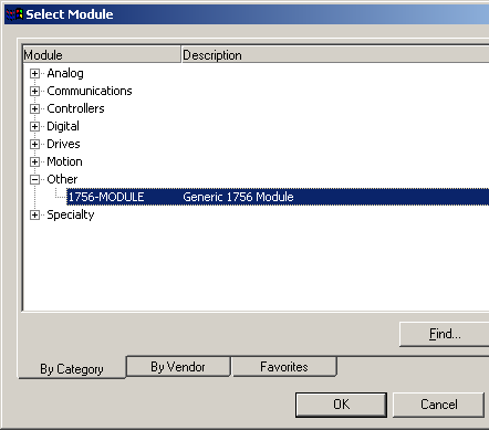
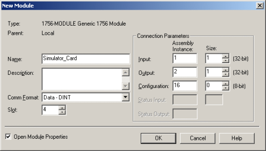
Next we’ll add some input/output simulation.
The chassis monitor will now have two emulation modules in it ready to go. 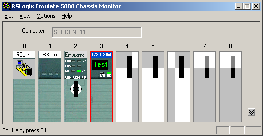 Creating a connection in RSLinx
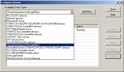 Using RSLogix Emulator in a ProjectTo use the emulator in a project you must setup the hardware correctly.
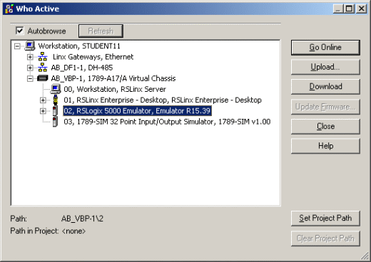
Ready, Set, GoYou are now ready to use the emulator just like you would any other PLC. Open Who Active and set the path to the RSLogix 5000 Emulator.
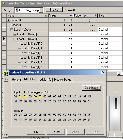
 The inputs can be simulated in the emulator’s Chassis Monitor by right clicking on the module and selecting Properties. Under the I/O Data tab is the ability to toggle each of the inputs on or off.
 Note:
RSLogix Emulator is sometimes erroneously called RSEmulator.
( categories: )
|
l;l
What is Ladder Logic?
Confused
I know this is going to sound stupid, but I am so very used to the old addressing system in the SLC 500 and older Siemens PLC's that I cannot get the newer stuff down. I would like to know, if I am troublshooting and think I have a bad outout on Control Logix using RSLogix 5000 hw do I know or fond out what input or output the tag name database is attached to? The older stuff I knew where the physical address was but with this I am lost. Any help would be great.
The tags for I/O is in this
The tags for I/O is in this format:
[Chasis Name].[Slot Number].[Input or Output].[Type of Data].[Terminal #]
Error in Connection Parameters screenshot
In the table listed for Connection Parameters you have the correct info,
However in your screen shot, you show the Size of Input as 1 instead of 2.
Chassis Monitor
Under the chassis monitor i can't seem to pull throught the I/O controls. I can open the I/O controls under the emulator, but this tab is not pulled through to RSLogix 5000. Everything else here works perfectly - any thoughts.
Cheers
Stew
chassis monitor
Tenho um program do RSLOGIX emulaTE 5000 CHASSIS E TBM TENHO O CONTROL LOGIX 5000 MAS NÃO CONSIGO ABRIE O EMUTATE, ENTRA UM TELA DIZENDO, (UNABLE TO READ VIRTUAL BACKPLANE STATUS.PLEASE MAKE SURE THAT RSLINX CLASSIC IS INTALALLED AND VIRTUAL BACKPLANE DRIVE IS RUNNING.)ALGUEM PODE ME AJUDAR COMO RESOLVO ESSE PROBLEMA.
OBRIGADO.
Thanks..It worked really
Thanks..It worked really well...But whenever I try to increase the no. of inputs more than 2 and go online , the no. of inputs set to 2 only instead of my specified number.
Hows it possible to emulate more than one inputs. This is because when you see the I/O data tab in the 1789-Simulator module , we can change only one input.
Any suggestions?
I/O configuration
Hello All,
I am trying to understand a little more about the Emulator.
Let's say I have RSLogix5000 program with all the I/O cards already configured (Not the simulated but actual I/O card). So when I am ready to download the program I know I have match the processor slot # to match with the Emulator processor slot #. But do I have to delete the actual I/O tree configuration inside the program since the Emulator does not have the I/O cards configured? or it does not matter, it will simply ignore the I/O configuration?
Thanks!
YOU CAN DELETE THE IO
YOU CAN DELETE THE IO MODULES FROM IO CONFIGURATION ONLY IN OFFLINE MODE AND THEN DOWNLOAD IT.
Estou com o mesmo problema.
Estou com o mesmo problema. Como vc o resolveu?
Tks
Muito obrigado pelo tutorial muito bom ótimo, deu certo aqui para cofigurar. com este eu configurei e agora estou simulando minha I/O..
agradeço
HAHAHAHAHHA SPANISH !
HAHAHAHAHHA SPANISH !
for full help of RSLogix
for full help of RSLogix Emulator 500 visit
www.RSLogixEmulator500.blogspot.com
First, thanks for this
First, thanks for this tutorial, it really helped me figure out how to us the RSLogix Emulate program. I was having problems getting the I/O modules working, your info on how to configure them really helped.
Second, I think the right URL for the blog referenced above is http://rslogixemulate500.blogspot.com
Oh Yes....!! Thanks My Dear
Oh Yes....!!
Thanks My Dear Friend The Right URL Is:
http://rslogixemulate500.blogspot.com
RSEmulator500.blogspot.com
RSEmulator500.blogspot.com doesn't seem to be out there
Its Portuguese...
Its Portuguese...
That looks like Portuguese
That looks like Portuguese to me
Muito Bom
Obrigado...
hahahahaha idiot
emulator mode controllogix
dear sir,
i have done all the procedures what u have mentioned above but am not getting programming screen to do program,if possible help me.
thank u
First,you should confirm
First,you should confirm that the "input size" property of the
1789-SIM module is 2.Because the input in the "I/O DATA" property interface is for the latter double word--I.Data[1].For the same reason, make sure you use I.Data[1] in your program .OR, your toggle in 1789-sim module won't be reflected in the online program. Second, you have to change the emulater CPU to "run" mode when you plan to simulate your program. If you find you toggle in the 1789-SIM module can be reflected in rslogix 5000 ,but your program don't work, one possible reason is your emulater CPU is in "program" mode.
Don't work!!
I've followed exactly all the steps shown in this tutorial but, i CANT change the status into ladder program, into RSEmulate changed the status of the bits but into RsLogix 5000 do nothing.
Any help??
Hi, I have done all the
Hi, I have done all the procedures that you have mentioned above but I am not getting programming screen to do program, if possible help me please.