The PIDE (Enhanced PID) is an Allen Bradley Logix5000 family (ControlLogix, CompactLogix, FlexLogix, SoftLogix) function block that improves on the standard PID found in all their controllers. First impressions of this function block are quite intimidating. If you try to dive into it head first you may just end up banging your head against a wall. Many will be quite happy to stick with the tried and true PID instruction but to compete with the more advanced process control applications the PIDE boasts the following.
- It uses the velocity form of the PID algorithm. This is especially useful for adaptive gains or multiloop selection.
- Control of the instruction can be switched between Program and Operator modes.
- Better support for cascading and ratio control.
- Built in autotuner (requires extra key)
- Support for different timing modes
- More limiting and fault handling selections.
Still interested? What we want to do here is basically get you off the ground with the PIDE, distill all the options to the essentials and get it working.
The PIDE is only available as a function block (sorry, no ladder). Like the PID instruction it is best to set it up in its own periodic task. The period of the task automatically becomes the sample rate (DeltaT) of the PID loop. Just make sure when adding the new routine to the task to select the Type as "Function Block Diagram."Â
Adding the PIDE Function Block
The PIDE instruction can be added from the Instruction Toolbar under the Process tab.
Once you plop a function block onto a sheet it automatically creates a program tag for the instruction which stores all the settings. The parameters can be set or monitored by wiring input and output references or by clicking on the ellipsis box in the top right corner to reveal the block properties.Â
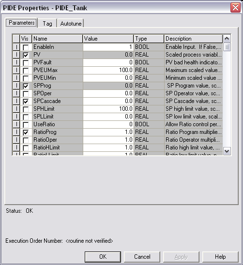
Opening the block properties for the PIDE instruction before RSLogix5000 version 15 meant you would be accosted with a long list of parameters.
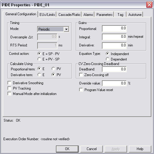
Version 15 has at least organized some of the more common settings (but not all) under tabs and groups.
Â
The most essential settings are:
|
Name
|
V15 Location
|
Description
|
|
.PV
|
Must be wired in from a tag.
|
The Process Variable is the reading (temperature, pressure, flow, etc.) that is to be controlled by the PID loop.
|
|
.PVEUMax
.PVEUMin
|
EUs/Limit tab in the Engineering Units Scaling group
|
The Process Variable Engineering Units Maximum and Minimum. The value of PV and SP which corresponds to 100 % span of the process variable.
|
|
.SPProg
.SPOper
|
Should be wired in or set in the tag.
|
The Set Point is the theoretical perfect value of the process variable. SPProg is the value to use when in program mode and SPOper is used when in operator mode.
|
|
.SPHLimit
.SPLLimit
|
EUs/Limit tab in the SP Limits group
|
The Set Point High Limit and Set Point Low Limit clamp the maximum and minimum values of the set point. If SPHLimit > PVEUMax or SPLLimit < PVEUMin then a fault will occur.
|
|
.PGain
|
General Configuration tab in the Gains group
|
Proportional gain. Enter 0 to disable.
|
|
.IGain
|
General Configuration tab in the Gains group
|
Integral gain. Enter 0 to disable.
|
|
.DGain
|
General Configuration tab in the Gains group
|
Derivative gain. Enter 0 to disable.
|
Program/Operator Control
The first thing to understand when programming a PIDE block is the different controls and modes available.Â
The Program/Operator control lets you transfer control of the PID loop between the user program and an operator interface such as an HMI. Each control has separate set points and mode controls. It's important to understand that when in Program Control the set point is determined by SPProg while in Operator Control its SPOper. The SP output indicates the set point that the function block is actually using.
Control is determined by the following inputs:
|
Name
|
Description
|
|
.ProgProgReq
|
A program request to go to Program control.
|
|
.ProgOperReq
|
A program request to go to Operator control.
|
|
.OperProgReq
|
An operator request to go to Program control.
|
|
.OperOperReq
|
An operator request to go to Operator control.
|
The ProgOper output indicates the control of the PIDE instruction. If the output is a 1 then it is in Program control and if the output is a 0 then it is in Operator control. The Program request inputs take precedence over the Operator requests so that the program can lock out any operator overrides. The ProgValueReset input clears all input requests.
Operating Modes
The PIDE instruction supports the following modes.
|
Mode
|
Description
|
|
Manual
|
While in Manual mode the instruction does not compute the change in CV. The value of CV is determined by the control. If in Program control, CV = CVProg and if in Operator control, CV = CVOper. Select Manual mode using either OperManualReq or ProgManualReq. The Manual output bit is set when in Manual mode.
|
|
Auto
|
While in Auto mode the instruction regulates CV to maintain PV at the SP value. If in program control, SP = SPProg and if in Operator control, SP = SPOper. Select Auto mode using either OperAutoReq or ProgAutoReq. The Auto output bit is set when in Auto mode.
|
|
Cascade/Ratio
|
While in Cascade/Ratio mode the instruction computes the change in CV. The instruction regulates CV to maintain PV at either the SPCascade value or the SPCascade value multiplied by the Ratio value. SPCascade comes from either the CVEU of a primary PID loop for cascade control or from the "uncontrolled" flow of a ratio-controlled loop. Select Cascade/Ratio mode using either OperCasRatReq or ProgCasRatReq. The CasRat output bit is set when in Cascade/Ratio mode.
|
|
Override
|
While in Override mode the instruction does not compute the change in CV. CV = CVOverride, regardless of the control mode. Override mode is typically used to set a "safe state" for the PID loop. Select Override mode using ProgOverrideReq. The Override output bit is set when in Override mode.
|
|
Hand
|
While in Hand mode the PID algorithm does not compute the change in CV. CV = HandFB, regardless of the control mode. Hand mode is typically used to indicate that control of the final control element was taken over by a field hand/auto station. Select Hand mode using ProgHandReq. The Hand output bit is set when in Hand mode.
|
If a fault occurs in the PIDE settings then it is forced into Manual mode and sets a corresponding bit in the Status words. The InstructFault output is the indicator of a fault. For more detail open the block properties and look at the Status at the bottom of the dialog box. Refer to the Logix5000 Controllers Process Control and Drives Instructions (pub 1756-RM006D-EN-P) for details.
Basic Example
Here's an example where just the essentials are used. This is a temperature control application if you hadn't guessed all ready. I've changed the look of the function block by going into the block properties, selecting the Parameters tab and checking on (or off) the boxes in the Vis column besides the inputs and outputs that are of concern.
Here's the run down on each of the inputs.
| Input |
Description |
|
PV
|
The process variable coming in from my TC card
|
|
PVEUMax
PVEUMin
|
The span of the temperature input that equals 0 to 100%. In this case the temp goes from 0 to 1200 degC.
|
|
SPHLimit
SPLLimit
|
We could limit the set point but in this test case just set it equal to the PVEUMax/Min.
|
|
SPProg
|
I've decided to use Program Control so the Set Point needs to come in on this input rather then SPOper.
|
|
CVProg
|
When in manual mode the CV is controlled by this input.
|
|
DependIndepend
|
I prefer the Dependent form of the PID algorithm.
|
|
PGain
IGain
Dgain
|
The essential PID settings of Proportion, Integral and Derivative.
|
|
ProgProgReq
|
Set the request to use Program Control.
|
|
ProgAutoReq
ProgManReq
|
Since we're in Program Control these inputs control the Auto and Manual modes. To run them off one switch the BNOT block is used to invert the bit.
|
Now for the outputs.
| Output |
Description |
|
CVEU
|
The Control Variable output in engineering units. Every PID control needs an output. In this case it goes from 0 to 100%.
|
|
SP
|
The actual set point which in this case equals SPProg.
|
|
ProgOper
|
I want to see a 1 here just to make sure we're in Program Control
|
|
Auto
Manual
|
Indicates the operating mode.
|
|
InstructFault
|
If I screw something up then this bit will come on.
|
Common Problems
|
No output
|
- The PID loop is in manual mode. Put it into auto mode using ProgAutoReq.
- Not in program control or SPProg is not set. Use ProgProgReq to go into program control and set SPProg.
- No values or not enough proportion (PGain) or integral (IGain).
|
|
Output is limited at 100
|
- The SP High Limit is still set at the default of 100. Change the value of SPHLimit.
|
Conclusion
Hopefully this basic introduction has gotten you off the ground. Half the battle is just getting it to work. Once that is done you can now really start to tinker with the power of the PIDE function block.
Further Reference
- Logix5000 Controllers Process Control and Drives Instructions (Publication 1756-RM006D-EN-P)
- Using the PIDE Instruction (Publication LOGIX-WP008A-EN-PÂ - August 2005)
- Using a Logix Controller for Barrel Temperature Control on Plastic Injection Molding and Extruding Machines (Publication RA-AP015A-EN-P €“ February, 2004)
hiiiiiiii
very good site which will helped me lot
Thats Informative,,,,
Thats Informative,,,,
Wow !!!
That's really Excellent information !
Assuming we have an HMI
Assuming we have an HMI under the MANUAL mode(from which the operator enters a value for the CV )...
Please correct me if I'm wrong:
-ProgProg must be ALWAYS true.
-When we want to go in the AUTO mode, that is to say, the program routine assumes the control of the PIDE and NOT the HMI , then ProgAutoReq=1
-Just the opposite: We want to go in MANUAL mode, then ProgAutoReq=0 and ProgManReq=1
Is it so easy like this??
PIDE
For Auto/Manual selection from HMI just latch OperOperReq.
then latch OperAutoReq and unlatch OperManualReq and viceversa.
Unlatch OperOperReq and Latch ProgProgReq for No controll from HMI.
PID-E Manual operation
Currently the PIDE I built in AB compactlogix functions well on Auto.
On manual,(by setting the opermanualreq), how do I change the output CV or CVEU??
The CVEU stays in the value when I took the PIDE on manual, even when I try to change it from watch screen.
Same way how do I change the setpoint on Auto??
Do I have to set some additional booleans or floats to the PIDE to change output?
I don't have an HMI, but trying to test on the Compactlogix running mode with watch screen.
I am stuck pl. help.
SM
hi
you cannot able to change the cveu since this parameter is linked with cv.kindly connect your tag which associated to cv to cvprog
Thank you
Thanks for knowledge.
:)
How auto-tune compute the PID Gains?
Thank you for this article, this very useful for me.
I want to know how PIDE auto-tune compute the PID Gains?
Can any one help me, thanks a lots
PIDE is too often overkill
Unfortunately, too many people are using the PIDE instruction where the simple PID ladder logic based instruction would more than suffice. I have spent countless hours with engineers and techs that utilized the PIDE instruction but were too soon over their heads with it. After showing them what the PID would do, they walked away from the PIDE.