PLC Programming HandbooksPopular ArticlesNavigationUser login |
Sequential Function Charts for AllImplementing Sequential Function Chart Designs using Ladder Diagram Programming Language for Programmable Logic Controllersby James McWhinnie ABSTRACTSequential Function Charts (SFC’s) have long been established as a means of designing and implementing sequential control systems utilising programmable controllers. The Programming Standard IEC 61131-3 includes a graphical implementation of SFC’s in its suite of programming languages. Many manufacturers offer programming environments that allow engineers to programme controllers using graphical methods to implement the SFC’s. However as well as the initial cost outlay there are overheads to be paid for in terms of computational speed, programme size and programme control. This facility is therefore usually only offered on the larger more powerful controllers where execution speed and programme size are rarely an issue. This paper demonstrates how SFC’s may be implemented on any PLC including low cost PLC’s with the simple Ladder Diagram programming language, with little computational overhead. Thus allowing the user all the benefits of using SFC’s in the design process. Keywords: Control, Finite State Machine(FSM), Sequential Function Charts(SFC), Programmable Logic Controller (PLC). 1.0 IntroductionMany systems have sequential operation requirements and Sequential Function Charts (SFC’s) have become a popular method of accurately specifying sequential control requirements. SFC’s have many advantages for software development both in the design stage as well as the implementation and testing, maintaining and fault finding stages. Design Stage
Implementation
Maintenance of Software
Machine Maintenance
After a brief introduction of SFC’s to the reader, this paper will show how to implement the charts using Ladder Diagram (LD) programming language. Then will go on to discuss how fault diagnosis and predictive fault diagnosis can be achieved. 2.0 Sequential Function ChartsThis section will briefly explain the SFC and demonstrate how it can be used to specify control requirements by an example. Then a method of implementing SFC designs will be outlined and demonstrated. Sequential Function Charts break a sequential task down into Steps, Transitions and Actions. These are drawn graphically to describe a sequence of interactions, as shown in Fig 1 below. Convention states that flow through an SFC is from top to bottom unless indicated by an arrow.
The sequence is broken down into steps (or states) where actions are carried out. The transition conditions define logical conditions that cause the process to move from the existing step to the next step. Actions contain three fields as shown in Fig2.
An Action consists of a qualifier which defines what type of action e.g. S for set, R for reset and N for continuous while in step. A description of the action or tag name and finally the address acted on. As the design progresses more detail can be added as shown Fig 3. This detail would include memory (%M), input (%I) and output (%Q) address information.
2.1 ImplementationIt is important when designing software for a PLC that the designer is aware of the operation of the ‘scan’. The PLC scan typically consists of the following sequential operations: Reads in the states of external devices into an area of memory designated input (I) memory. Evaluates user programme writing output results to memory (M) and output memory (Q). The output memory is then used to drive the real physical outputs, Fig 4.
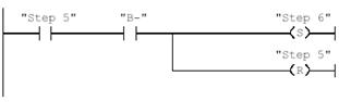
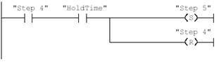
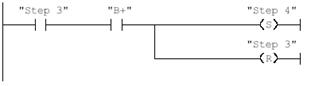
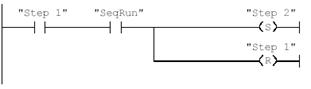
Figure 4: Typical PLC Scan When implementing SFC’s using Ladder Diagram (LD) the step and transition logic can be treated separately from the action logic. The Ladder Diagram logic for a typical step is shown in Fig 5.
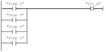
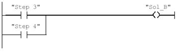
Each step can be entered from at least one step. If it can be entered from more than one step then all possible previous steps must be reset. Once the Step/Transition logic has been completed then the actions can written. In a simple system outputs can be driven directly from the states as shown in Fig 6.
To illustrate the use of SFC and how they may be implemented let us consider a simple example. Two pistons as shown in Fig 7 have to be controlled using a PLC. The operation requirements are as follows. When a normally open switch (%I0.7) is closed momentarily and both pistons are home the following sequence should occur:
The sequence does not operate until the switch is closed again i.e. it operates every time the switch is closed and if piston A is in its home position.
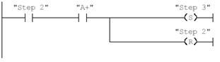
Taking the written description, a SFC can be drawn. As the inputs and outputs have been assigned detailed memory information can be included, as shown in Fig 8.
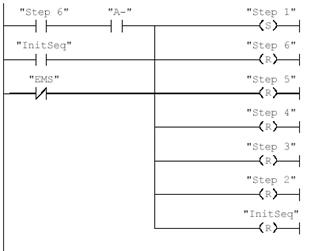
From this the Step/Transition code can be written as shown in Fig 9. Note the Step logic is entered in reverse order to ensure that a sequence is entered for at least one PLC scan (ref.).
Step 1 Contains additional logic, the “InitSeqâ€, a one shot (is true for first scan) signal is used to place the system into step 1 when the PLC is first switched on or moved from stop to run and the Emergency Stop input is used to drive the system into step 1 which in this case is considered to be the safe state. Note also that all other states are reset, this is necessary as for example an Emergency Stop could happen in any step. Next is the software to drive the outputs. This is relatively simple as shown in fig 9.
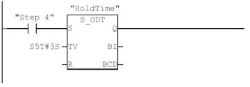
Logic is also required for sequence start condition logic. 3.0 Fault DiagnosticsThe use of SFC’s has advantages when testing and commissioning control system software. One of the features of Programmable Logic Controller programming systems is the ability to monitor programmes and variables online. This allows the engineer to monitor the step progress by viewing the appropriate memory bits. If the machine stops the current step can be easily identified and by viewing its logic network, it is a staright forward task to identify which transition conditions are not being met. This can then identify the areas requiring investigation. The use of step/state monitoring can then be used to trigger alarm conditions automatically. For example, each step/state duration may be timed. If the duration exceeded limits this could be used to identify a fault possibly either with the control action or transition signals. More advanced analysis of the step/state times could be used to warn or predict a failure mode or identify maintenance requirements. Consider the above system; the duration the system is in Step 2 may indicate the health of the pneumatic piston. i.e. if the time gets longer it may indicate an air leak. This could be used to request maintenance to check at the next opportunity. A combination of step time deviations may help predict a looming specific component failure. ( categories: )
|


Hi. SFC is in IEC1131
Hi. SFC is in IEC1131 standard. Why bother to look for a way to replace it with out-dated languange (LD)? Imho, it is masochism to do it...
Missing point of article. In
In reply to comment. Reader is missing point of article. In practice not all PLC's offer IEC61131-3 compliance, and in particular SFC's (not strictly a language), however they almost all provide LD. This article just shows a reliable method of implementing SFC designs.
hey, we live in 2008, not
hey, we live in 2008, not 1998. Even Siemens has SFC. IMHO, author missed the point when he started to write this article - it is late 5 to 10 years :)
Still relevant for many companies
There are some very large global companies that actually require this type of programming on supplied equipment. The old adage of "the customer is always right" fits in here. I will program that way if they are paying for it.
this article is very applicable for low cost hardware
There are many applications for low cost PLC's and the $150 smart relay's where this is very useful. Those devices do not support SFC.
"Even Siemens has SFC." What
"Even Siemens has SFC." What on Earth does this mean?
I remember using SFCs in Siemens S5 equipment 20 years ago with their software package Graph 5. OK so it wasn't IEC61131 compliant but IEC1131 (or its predecessor for SFCs IEC948) didn't even exist then.
who missed the point ???
since Sun, 2008-08-31 13:59 , I was waiting for an enlightment from 'bala nemate' , an alternative to James' article , wich I found an intuitive synthesis on the SFC subject. This is what most people are doing today : it is very easy and convenient to deny an article / statement instead offerring better alternative to it.
Thank you , James , what you said , remains . All the rest ... is sillence.
A Good Year , to all !
Your comments are
Your comments are appreciated.
More then one step in one scan
I am using state machine in ladder logic for more then 20 years. I see some problems with this "set / reset" implementation: 1)if all condition are true you could have a few steps resolving in one PLC scan. As a result other part of the program never see these steps. 2) Nothing prevent more than one step bit (coils) to be on at the same time. 3) there is no simple way to pause, or single step the state machine. 4) there is no one data register to monitor the current step.
I have used the DECODE instruction to resolve all the above issues.
Hillel Sorry I havent got
Hillel
Sorry I havent got back to you sooner have not checked site for a while. I too have been programming PLC's and controllers for 20+ years and this has worked well for me. Especially when under pressure its good to have a proven design method to work with. I have used it from single machines to complete Water treatment works with multiple networked PLC's i.e. SFC's co-ordinating over the network.
Point 1) This is why the step logic is written in what appears to be reverse i.e. step 6 logic first then, so that any step will be valid for at least one scan even if the next transition is true.
Point 2)Only the logic controls this, however when you have parallel branching more than one step needs to be true.
Point 3)You would need to add logic if this was an issue. However when testing using a simulator which I would always do before going live, as you are controlling the transition logic I have not found this to be a problem. You can also force system into a step by writing to memory byte/word containing step flags.
Point 4) Most PLC's allow you to monitor memory in runtime and therefore you can follow the step progression. Also handy for relaying machine status on SCADA.
Hope this answers your points.
I still see some problems
Thank you James, for your reply.
1)I still see a problem with your "reverse order". In many cases the program jump back to an earlier step, not always forward. In large program, writing in reverse could be confusing for someone else to understand. In my approach I don't need to do this and it will never have more then one step in one scan.
3)Pause and single steps are needed for the final product not only for the programmer debug phase. In my approach it takes no additional programming, you just stop the decode function in order to pause, or decode with a one shot to single step.
4)I use to store the last 50 steps of the state machine, by a shift register that is shift when the step number is changed. This is very helpful, to figure out what happened in a system that lead to a problem. Again this is for the final product and not during debug.
Best regards, Hillel Hachlili
I suggest you read my
I suggest you read my article here 'An introduction to grafcets', where these issues are also resolved in a simple way. I do no know if this could be applied to a Siemens PLC, but I like to believe that it is possible. It gets rid of the SET/RESET functions, it prevents two steps in one cycle, and also guarantees that every step is active for at least one cycle.
SFC
ladder is much simpler. I made a plc program to do this example in 12 rungs. Probably could do in less. I dont see the benefit.
This simple exercise was
This simple exercise was only to illustrate the technique, of course it can be done with less logic. If you programme more complex systems its very easy to get confused and your code difficult to follow and fault find on, especially with multiple SFC's interacting with each other. This just gives a structured approach. If you don't need one great!